Eng-Tips is the largest engineering community on the Internet

Intelligent Work Forums for Engineering Professionals

  • Congratulations waross on being selected by the Eng-Tips community for having the most helpful posts in the forums last week. Way to Go!

How do you distribute seismic diaphragm force? 1

Status
Not open for further replies.

StructEngineer90

Structural
Jul 1, 2019
9
US
See attached...

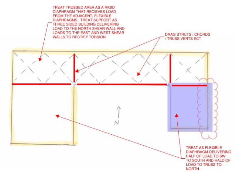
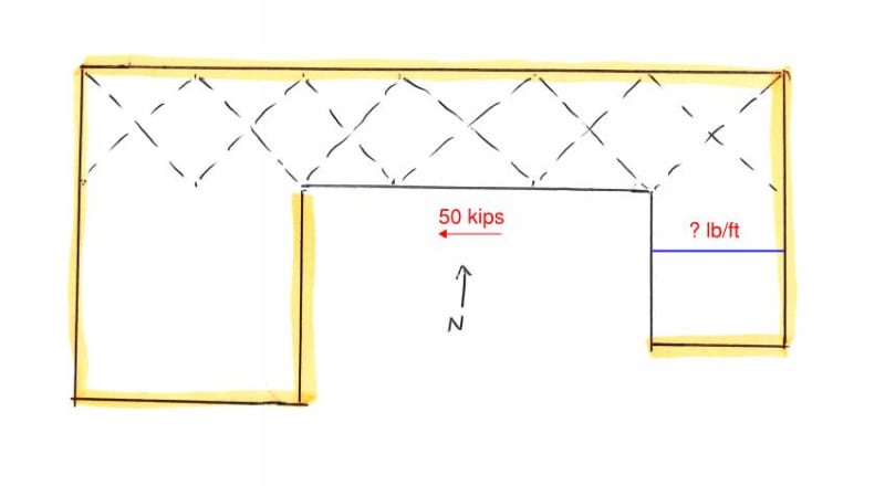
I have a roof diaphragm as shown. The yellow highlighted lines are shear wall locations. Dashed lines are horizontal braces. Wind load controls in the North-South direction (which required the horizontal braces). But in the East-West direction, seismic controls.

Question is, how do I distribute the seismic forces to design the deck connections (need to figure out diaphragm shear)? Do I need to divide up the total story diaphragm force into different parts? For example (in the attachment), should I figure out what the seismic force is of the East leg (in purple) using only seismic weight of that area including only the clouded portion of the shear wall? And then I'm assuming I would break it up similarly with the West leg and North portion.
 
 https://files.engineering.com/getfile.aspx?folder=8b92dcbc-8cbf-47a8-abd0-b6e48fcb8dcf&file=Diaphragm2.jpg
Replies continue below

Recommended for you

- What's the diaphragm construction in the portions of the roof where you're not showing discrete horizontal bracing? More bracing or does it switch to just plain roof deck somehow? This will be important to answering your question.

- A first step is to decide whether you intend to consider this a flexible diaphragm, a rigid diaphragm, or prosecute an envelope design that considers both cases. ASCE7 has some guidance with respect to when diaphragms are to be considered rigid vs flexible. Discrete, horizontal bracing pushes the needle towards rigid diaphragm treatment in my experience but, then, much depends on what the diaphragm construction is in the locations where you're not showing the bracing. The procedure that you've described sounds quite a bit like a flexible diaphragm load distribution.

- Are you concerned only with sorting out seismic in the E-W direction for the sake of this thread?

- What are you using for your framing member here? Steel joists? Glulam beams?

- At the re-entrant corners, are you planning to have any drag struts running into the body of the diaphragm?

 
Yes, I am mainly concerned with the seismic forces in the E-W direction. The entire roof construction will be 1 1/2" metal roof deck on steel beams but the horizontal x-bracing exists only in the North portion (for now).

I don't plan on having any drag struts since I think I'm providing enough shear walls to avoid that and I'm hoping an economically weld pattern can transfer the diaphragm shear forces.
 
It's a pretty complex thing really. If the stakes are high, such as in high seismic design, it might warrant an FEM investigation. If the stakes are low, I'd consider the approach shown below to be reasonable. It's really just a more developed version of your proposal.

c01_ph4zjr.jpg
 
Ah, that's what you meant by drag struts; I misunderstood. Yes, there will be chord members/truss "verticals" in the horizontal truss system.

That diaphragm system is kind of what I was envisioning. But to go back to my original question, is breaking up the seismic weights of the different portion to determine the seismic forces at the different parts of the diaphragm the right approach?

Thank you for your responses.
 
Hello StructEngineer90,

I've found the attached document to be helpful; the author also wrote an entire book dedicated to Diaphragm analysis titled, "THE ANALYSIS OF IRREGULAR SHAPED STRUCTURES"; it's been a very enlightening reference chalked full of numerous examples of how to provide a complete load path when confronted with most common irregularities.

As the attached paper indicates, Diaphragm design is often not taught in school and is frequently oversimplified in practice without consideration of how all the forces get taken to the ground. At a quick glance, it looks like you need to add what the attached paper refers to as "Transfer Collectors" to carry the additional "Transfer Diaphragm" forces induced by the re-entrant corners.

As the paper mentions, diaphragm design is often oversimplified; I don't believe it's a topic commonly covered in undergrad programs.

Hope this helps!
 
 https://files.engineering.com/getfile.aspx?folder=863ed277-88cc-425f-9701-e2854a848033&file=Irregular-Diaphragms_Paper-N_June2015.pdf
OP said:
But to go back to my original question, is breaking up the seismic weights of the different portion to determine the seismic forces at the different parts of the diaphragm the right approach?

I don't view that as a distinct question in its own right. The seismic weight simply is where it is physically and, once you've decided upon a load distribution model (flexible/rigid/load path), nothing else remains to be decided upon. To decide/consider that you can't break up the diaphragm discretely as you've proposed is really to revisit your decision about whether or not the diaphragms should be considered rigid in those areas to begin with.

 
Hmm... maybe I'm not asking the question the right way.
See below.
Say I have a seismic diaphragm force of 50 kips at this particular roof level. In order to design the fastener layout pattern for the east portion of the diaphragm, I need to know what the diaphragm shear is (in lb/ft along the blue line). Using the full 50 kips to determine the diaphragm shear would be overly conservative, correct? If so, how do I determine a more realistic diaphragm shear value?

Sorry if I'm being way off-base in my thought process. This is my first time coming across something like this so I'm still learning..

Diaphragm3_df8omx.jpg


Thank you, jochav52802, I will look into that!
 
OP said:
Using the full 50 kips to determine the diaphragm shear would be overly conservative, correct?

Definitely.

OP said:
If so, how do I determine a more realistic diaphragm shear value?

Mostly, as you proposed initially with treating individual roof sections separately. However, I think that it's crucial for you to understand why this is a reasonable thing to do. I'd recommend working through the diaphragm model that we've been discussing above in detail to determine your governing diaphragm shears. And then, ideally, review that with an experienced colleague. Or, alternatively, with those of us helping you here.

For seismic, I find it instructive to always be thinking of each individual square foot of a diaphragm in isolation. Its weight is its weight and it's located where it's located. Somewhat like water flowing, then, the only questions become where does it end up and by what path did it get there. And that's the rigid vs flexible diaphragm story for the most part.


My pleasure StructEngineer90,

It sounds like your Southwestern and Southeastern unbraced portions of the building are flexible diaphragms as per ASCE 7-10, Section 12.3.1.1, so I believe you would just need to determine how much of the 50-kips is being contributed by each of those areas and then simply apply half of the resulting loads equally to each side of the diaphragm.

For example, if the southeastern portion contributed 20-kips of the overall load, than 10-kips would go to the southern shear wall and the other 10-kips to the northern collector. You would then divide the 10-kips by the shear wall and collector length to come up with the unit force that your diaphragm anchors would need to resist.
 
Not sure if this will be useful to you but it has been to me: Link

 
Great link Kootk!

I've found one good thing to keep in mind is how ASCE 7-10, Section 12.3.1.2 defines a flexible diaphragm; in short, the diaphragm deflection must be at least twice the average drift of the vertical resisting system in order to be considered a flexible diaphragm. The point that sticks out to me is that when you combine a flexible diaphragm with a flexible vertical force resisting system, the forces will not distribute as a flexible diaphragm would based on tributary width, rather it would distribute semi-rigidly or rigidly, based on the stiffness of the vertical system, while also inducing the inherent/accidental torsion loads.

 
Status
Not open for further replies.

Part and Inventory Search

Sponsor

Back
Top