StructEngineer90
Structural
See attached...
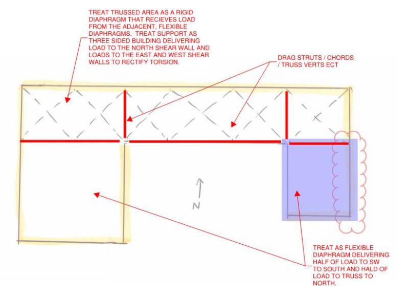
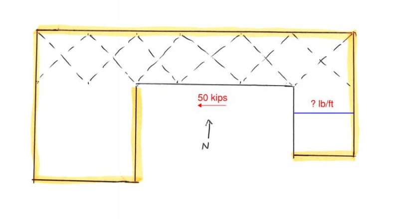
I have a roof diaphragm as shown. The yellow highlighted lines are shear wall locations. Dashed lines are horizontal braces. Wind load controls in the North-South direction (which required the horizontal braces). But in the East-West direction, seismic controls.
Question is, how do I distribute the seismic forces to design the deck connections (need to figure out diaphragm shear)? Do I need to divide up the total story diaphragm force into different parts? For example (in the attachment), should I figure out what the seismic force is of the East leg (in purple) using only seismic weight of that area including only the clouded portion of the shear wall? And then I'm assuming I would break it up similarly with the West leg and North portion.


