Nicholas Lee
Industrial
Whilst there are many examples of velocity control of Brushless DC (BLDC) motors on the web, I have been having trouble identifying exactly how to implement very accurate angular positional control.
I have a hardware setup with a BLDC motor, whose output shaft position is monitored by a very accurate absolute rotary optical encoder.
The current in each of its three coil windings is controlled from a 16-bit analog-to-digital converter (ADC). [i.e. precision analogue, not PWM controlled]
I understand the principle of converting the three winding currents (U, V ,W) into a single applied field vector (With a Magnitude and Direction) by means of Park-Clarke transforms etc.
I also understand that maximum torque is achieved when the applied field vector is 90 degrees ahead of the physical angular position of the rotor and that the torque falls to zero when the field vector is aligned with the rotor angle.
NB: There are no hall sensors in the motor, the position of the output shaft is measured with an absolute optical encoder.
My confusion arises partly because there is no externally observable way to accurately measure the physical angular offset between the magnetic field vector created by the phase windings inside the motor, and the zero-datum angle of the optical encoder attached to the motor shaft. This angular offset (call it Theta) is an unknown value, but it is constant, as the windings and the optical encoder are both physically connected to the motor shaft.
This unknown physical angular offset seems to be the main stumbling block to creating a positional feedback loop.
This is because Theta gets inherently added to the error value when subtracting the angle between the desired and the measured positional angle, and this messes up using that calculated error signal in the forward path of a any (PID) controller used to generate the required control signals.
In velocity control, the value of Theta would be irrelevant, but for positional control it matters.
Rearranging the system diagram, the unknown but constant offset theta is being added to the error, a bit like in this image.
Here, r(t) is the desired angle, y(t) is the angle of the shaft as measured by the optical encoder, and theta is the unwanted constant offset to be rejected.
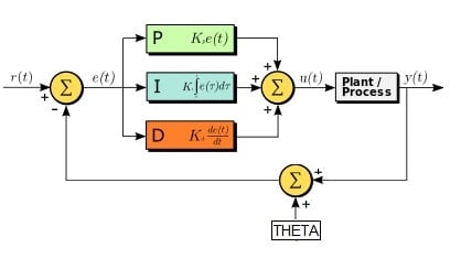
(Admittedly, the image does not represent how the 2 components of the field vector are generated, just the angular component)
Is there a way to auto-tune the system so as to evaluate what the angle Theta is?
Have I misunderstood the control problem entirely? Is there a better way to solve this?
Any help would be gratefully received.
I have a hardware setup with a BLDC motor, whose output shaft position is monitored by a very accurate absolute rotary optical encoder.
The current in each of its three coil windings is controlled from a 16-bit analog-to-digital converter (ADC). [i.e. precision analogue, not PWM controlled]
I understand the principle of converting the three winding currents (U, V ,W) into a single applied field vector (With a Magnitude and Direction) by means of Park-Clarke transforms etc.
I also understand that maximum torque is achieved when the applied field vector is 90 degrees ahead of the physical angular position of the rotor and that the torque falls to zero when the field vector is aligned with the rotor angle.
NB: There are no hall sensors in the motor, the position of the output shaft is measured with an absolute optical encoder.
My confusion arises partly because there is no externally observable way to accurately measure the physical angular offset between the magnetic field vector created by the phase windings inside the motor, and the zero-datum angle of the optical encoder attached to the motor shaft. This angular offset (call it Theta) is an unknown value, but it is constant, as the windings and the optical encoder are both physically connected to the motor shaft.
This unknown physical angular offset seems to be the main stumbling block to creating a positional feedback loop.
This is because Theta gets inherently added to the error value when subtracting the angle between the desired and the measured positional angle, and this messes up using that calculated error signal in the forward path of a any (PID) controller used to generate the required control signals.
In velocity control, the value of Theta would be irrelevant, but for positional control it matters.
Rearranging the system diagram, the unknown but constant offset theta is being added to the error, a bit like in this image.
Here, r(t) is the desired angle, y(t) is the angle of the shaft as measured by the optical encoder, and theta is the unwanted constant offset to be rejected.
(Admittedly, the image does not represent how the 2 components of the field vector are generated, just the angular component)
Is there a way to auto-tune the system so as to evaluate what the angle Theta is?
Have I misunderstood the control problem entirely? Is there a better way to solve this?
Any help would be gratefully received.