Continue to Site

Eng-Tips is the largest engineering community on the Internet

Intelligent Work Forums for Engineering Professionals

  • Congratulations KootK on being selected by the Eng-Tips community for having the most helpful posts in the forums last week. Way to Go!

How does pressure drop work in parallel? 2

n8cole

Chemical
Jun 24, 2024
29
Imagine you have two ducts (ducts 1 and 2) that merge into a single duct (duct 3). There is a fan located on duct 3 that needs to pull air through ducts 1, 2, and 3, and then exhaust it through duct 4. Both ducts 1 and 2 have obstructions that cause a pressure drop of 7 inches of water column (7"wc) each. Assuming these obstructions are the only cause of pressure drop, would the fan need to generate a suction of 7"wc or 14"wc? I am trying to figure out how pressure drop works in series.

Hopefully this process diagram I made clarifies my imaginary setup and question.
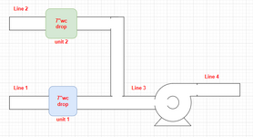
1733860426492.png

edit: As it has been pointed out below, I was mistaken when I referred to the above setup as "in series". The setup is in parallel. I changed the title to avoid confusing anyone else who stumbles on this thread. Thank you to everyone who pointed that out to me.
 
Last edited:
Replies continue below

Recommended for you

The way to look at it is that the pressure at the connection point of line 1 and 2 to 3 can only be one value. So if both lines 1 and 2 are taking flow from atmosphere at 0 psig then the flow in each branch 1 and 2 is determined by the pressure drop in each branch (restriction to flow). In your example you show that the line losses are negligible but there is an equal pressure drop (restriction to flow) in each line segment across some device. Therefore there will be an equal flow in each line segment because the flow will increase in each line segment until the pressure at the common connection point is the same. This assumes that the both units 1 & 2 give the same pressure drop at same flow and are equally sized. Now if the unit 1 and 2 were different sized and produce different pressure drops at different flow then the flows in each line 1 and 2 will be determined when the pressure drop is such that the same pressure exists at the connection to line 3 as there can only be one pressure at that point.

For parallel flow (what you show above) the pressure drop at the common connection point must be same. Pressure drops don't add for parallel flow but are what they are in each branch independently of the other but where they combine they must be equal. So if the intake is at atmospheric in your case the pressure at the common connection point is negative 7" wc. at the given flow. So if the fan discharges to atmosphere it must develop 7" wc differential pressure.

If the two branches above were arranged in series so that the same flow goes through both units 1 & 2 then the total pressure drop adds and therefore would be 14 inches wc total and pressure at connection to line 3 would be negative 14" wc., so differential pressure required of blower would be 14" wc for discharge to atmosphere.
 
Last edited:
This is meaningless without knowing what the flow is to create the 7" of pressure drop. At zero flow the pressure drop is zero.

Without knowing what the pressure drop is in the pipe is not possible to say what is likely to happen.
 
Uh, this is a parallel arrangement, not series.

If the blue thing and the green thing are identical, then the flow and pressure drop will be the same.

The pressure drops do not add.

That's how single fan distribution systems are balanced. Adjust the pressure loss to be equal to equalize the flows.
 
This is meaningless without knowing what the flow is to create the 7" of pressure drop. At zero flow the pressure drop is zero.

Without knowing what the pressure drop is in the pipe is not possible to say what is likely to happen.
Assume any flow you want. What I want to know is does the fan need to be sized for 7"wc or 14"wc static pressure. This is ignoring that fact that I would need to know desired suction pressure at the inlet of unit 1 and 2, and the desired outlet pressure of the fan.
 
Assume any flow you want
No. You don't get to do that.

Flow and pressure drop are related.

You need to match the characteristic of the system and the characteristic of the fan to cross at the pressure vs. flow point that you need.
 
The way to look at it is that the pressure at the connection point of line 1 and 2 to 3 can only be one value. So if both lines 1 and 2 are taking flow from atmosphere at 0 psig then the flow in each branch 1 and 2 is determined by the pressure drop in each branch (restriction to flow). In your example you show that the line losses are negligible but there is an equal pressure drop (restriction to flow) in each line segment across some device. Therefore there will be an equal flow in each line segment because the flow will increase in each line segment until the pressure at the common connection point is the same. This assumes that the both units 1 & 2 give the same pressure drop at same flow and are equally sized. Now if the unit 1 and 2 were different sized and produce different pressure drops at different flow then the flows in each line 1 and 2 will be determined when the pressure drop is such that the same pressure exists at the connection to line 3 as there can only be one pressure at that point.

For parallel flow (what you show above) the pressure drop at the common connection point must be same. Pressure drops don't add for parallel flow but are what they are in each branch independently of the other but where they combine they must be equal. So if the intake is at atmospheric in your case the pressure at the common connection point is negative 7" wc. at the given flow. So if the fan discharges to atmosphere it must develop 7" wc differential pressure.

If the two branches above were arranged in series so that the same flow goes through both units 1 & 2 then the total pressure drop adds and therefore would be 14 inches wc total and pressure at connection to line 3 would be negative 14" wc., so differential pressure required of blower would be 14" wc for discharge to atmosphere.
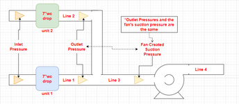
Embarrassingly, after rereading your post for about 30 minutes, I finally got it. The way I now like to think about it is in terms of inlet and outlet pressures. The outlet pressure of both units 1 and 2 is created by the suction of the fan. This suction pressure exists in line 3 and therefore exists in lines 1 and 2 after units 1 and 2 (as you explained in your post). If this suction was -7"wc, then it could overcome the pressure drop resistance caused by both units 1 and 2, since both units 1 and 2 would have an outlet pressure of -7"wc.

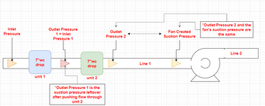
Where this way of thinking really helps me is when used and compared to pressure drop in series. Take the same example but with one line (line 1), unit 1, and downstream of unit 2. The suction created by the fan (-7"wc) is the outlet pressure to unit 2 and is enough to overcome the pressure drop resistance caused by unit 2. However, to do this would require all the energy available by the suction; therefore, there would be no suction left to overcome the pressure drop resistance of unit 1. In order to do that, the fan would need to generate a 14"wc suction (-14"wc). 7 + 7 - 14 = 0.

I erroneously simplified the principles at play here, but it makes sense.

I also made updated diagrams to again help explain my nonsense.
1733883194654.png
1733883178991.png
 

Attachments

  • 1733882934177.png
    1733882934177.png
    33.5 KB · Views: 0
You still seem to be missing that flow and pressure are related. You won't be able to understand this until you let go of the incorrect belief that flow and pressure are independent.

Plenty of resources on the web will explain about the interaction between the "fan curve" and the "system curve".

understanding_your_system_resistance.jpg


You're probably further confusing yourself with the sign conventions you are using, treating a pressure drop as a positive number, visualizing suction as "pushing", etc.

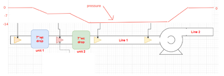
The pressure will look like this:
Screenshot 2024-12-11 1.33.48 PM (2).png
 

Attachments

  • Screenshot 2024-12-11 1.33.48 PM (1).png
    Screenshot 2024-12-11 1.33.48 PM (1).png
    75.4 KB · Views: 1
Embarrassingly, after rereading your post for about 30 minutes, I finally got it. The way I now like to think about it is in terms of inlet and outlet pressures. The outlet pressure of both units 1 and 2 is created by the suction of the fan. This suction pressure exists in line 3 and therefore exists in lines 1 and 2 after units 1 and 2 (as you explained in your post). If this suction was -7"wc, then it could overcome the pressure drop resistance caused by both units 1 and 2, since both units 1 and 2 would have an outlet pressure of -7"wc.

Exactly. Because units 1 and 2 are in parallel so pressure downstream must be equal.

Where this way of thinking really helps me is when used and compared to pressure drop in series. Take the same example but with one line (line 1), unit 1, and downstream of unit 2. The suction created by the fan (-7"wc) is the outlet pressure to unit 2 and is enough to overcome the pressure drop resistance caused by unit 2. However, to do this would require all the energy available by the suction; therefore, there would be no suction left to overcome the pressure drop resistance of unit 1. In order to do that, the fan would need to generate a 14"wc suction (-14"wc). 7 + 7 - 14 = 0.

Yes, the suction pressure would be negative 14" wc at suction of fan since this is the total friction loss in the total suction line. The pressure between the units will be negative 7" wc since this is the pressure drop across unit 1 and upstream pressure is atmospheric = 0" wc.
 
Last edited:
Hi,
To avoid this type of question, use always absolute pressure to describe your system.
At the intersection of ducts, the pressure is the same. You need to balance the flowrates in the different ducts to get your answer.
Excel is a good tool for such application , using solver.
Good luck
Pierre
 
You still seem to be missing that flow and pressure are related. You won't be able to understand this until you let go of the incorrect belief that flow and pressure are independent.

Plenty of resources on the web will explain about the interaction between the "fan curve" and the "system curve".

understanding_your_system_resistance.jpg


You're probably further confusing yourself with the sign conventions you are using, treating a pressure drop as a positive number, visualizing suction as "pushing", etc.

The pressure will look like this:
View attachment 2215
You are right! But I knew this. Granted, my understanding of the relationship between flow and pressure could easily be used as an example of the Dunning-Kruger effect. I just find it easier to understand if I think of the suction as something consumed by the pressure drop. I know it is not technically correct, but it helps me visualize the pressure drop as a barrier or a block of mass, and the suction pressure as the force required to break that barrier or move that block. Once the barrier is broken, the flow can proceed through the line/system.

That said, your graphical representation of the pressure is very helpful in understanding what is actually going on with the gauge pressure, so I thank you for that!
 
No. You don't get to do that.

Flow and pressure drop are related.

You need to match the characteristic of the system and the characteristic of the fan to cross at the pressure vs. flow point that you need.
I created this post to help me better understand how to deal with pressure drop in parallel. Can you explain to me why I need to define a fictitious flow for this fictitious and extremely simplified example scenario?
 
I think because you stated one thing in numbers (pressure drop), we thought that this was a real situation, not just made up....
 
I think because you stated one thing in numbers (pressure drop), we thought that this was a real situation, not just made up....
I apologize for the confusion. I thought assigning made up values would help to clarify my question.
 

Part and Inventory Search

Sponsor