Continue to Site

Eng-Tips is the largest engineering community on the Internet

Intelligent Work Forums for Engineering Professionals

  • Congratulations KootK on being selected by the Eng-Tips community for having the most helpful posts in the forums last week. Way to Go!

How shallow an angle of V would still align with a round metal bar? 3

Status
Not open for further replies.

ship69

Mechanical
Nov 23, 2015
22
Hello

I am new. I have simple a mechanical design problem:

1. I have a cylinder - i.e. a round bar - that is 25mm in diameter and made of polished metal (chrome).

2. I have an inverted V shaped guide made from smooth plastic (probably polyethyline PE or similar. This inverted V will be fairly short - only 10mm (1cm) deep.

Now, the plastic inverted V shaped guide will be resting (unsupported) on top of the round bar, with a light force equivalent to say 200 grams, and it will be able to twist along a vertical axis.

My question is this:
How shallow can I allow the angle of inverted 'V' to be and still expect the V to rotate so as to align with the direction of the metal bar? i.e. to point in the same direction. (The alignment of the two objects only needs to be within a few degrees)

To explain:
If the V is extremely steep say 45 degrees - or even 90 degrees - then it would be reasonable to expect the V to align EXACTLY with the bar. But if the V is very shallow and starts to approach 180 degrees, then one would not expect the V to rotate at all.

Are there any rules of thumb or guestimates that I could use?

J

P.S. Please excuse the very crude nature of the attached diagram, but I hope it brings the problem to life...
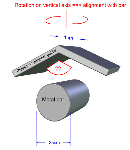
delme-guide02_ozu5xo.jpg
 
Replies continue below

Recommended for you

I do not know of any rule of thumb. I would expect the coefficient of friction would determine when the V will no longer, reliably align with the cylinder. The aligning forces, given your downward force, would no longer exceed the friction forces and there would not be enough force to cause the V to rotate to align.

Ted
 
What is preventing the round rods from rotating? THAT will determine how force you need to keep the angle iron and the bar aligned against the resisting torque.

For example: Short, round bar is on a sheet of smooth ice, at melting point. Almost no resisting force at all.

Long round bar is welded (glued) to a piece of steel plate. Near-infinite resistance to torque.
 
Apologies it seems I wasn't clear enough.

> I would expect the coefficient of friction would determine when the V will no longer, reliably align with the cylinder.
With all due respect, this is not telling me anything new! What I need is to make a reasonable 'guestimate' for my first prototype.
i.e. Yes, the coefficient of friction is important - clearly. Fwiw, in this case I said it was PE - polyethylene - which as we all know has a very low coefficient of friction. However all the variables that I have supplied are important, including the depth of the V. If the v was very long, and if the V was a tight angle, then would become very easy. etc.

However in this case, the dept of the V is fixed at 1cm. The only real variable I have to play with is the angle of the V. And in order to save vertical space I need the V to be wide as possible...

To get clear, what I need help with is having a reasonable stab at what the design should be. Otherwise I will simply have to build endless, endless prototypes. And surely the whole point of the discipline of engineering is NOT to have to build endless prototypes in order to design things!

> What is preventing the round rods from rotating?
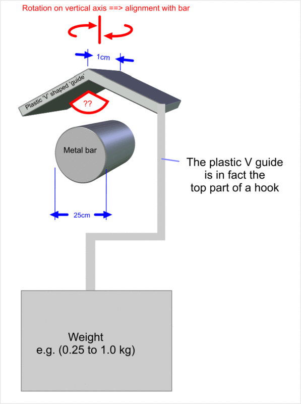
No, the rods are fixed in place and can not rotate at all. The V shaped plastic guide can rotate only a vertical axis. They can't rotate around a horizontal axis either. (To get clear, the reason for this is that the plastic V forms what is in effect the top section of a "hook" which goes over the metal bar. And the hook is kept in place by gravity. What I need to achieve is to find a way to make sure that the plastic hook ends up at EXACTLY (or almost exactly) 90 degrees to the the metal rod.

The only things that are stopping the V from rotating are:
a) Friction
b) If the plastic V rotates far enough around a vertical axis, eventually sides of the V will of course start to cross over the horizontal metal bar in a significant manner, and at this point to rotate any further would require the plastic V to start to be raised. Due to the weight at the other end of the hook this would require work to be done against gravity.

This is for an indoors consumer product. So there sill be little or now wind. Humans may occasionally bush very lightly against the plastic.


I think we are over-complicating this. Just want a V to be aligned along the side of a cylinder. And I want to know should it be: 5, 10, 15, 20, 30, 40 or 50 degrees!

J
 
The rod is smooth, right?

Is the V on a shaft or something like it so it will drop smoothly down onto the middle of the rod every time?
 
The plastic V guide is smooth - probably waxy poly ethylene.

The metal bar will be a fixed object - normally polished metal. (Although it may possibly be smooth painted/varnished wood.)

The V shaped plastic guide is the top section of a hook design and is held in place purely by gravity.

delme-v-guide_ml7pgh.gif
 
Make the included angle 120 degrees. The ramp out force will be .58 x the weight.

Ted
 
> Make the included angle 120 degrees.
Sounds reasonable...
I'm slightly confused about the rationale for 120 though.
How far will the vertical axis rotation need to proceed in order to get the your ramp out force?
 
Rotation beginning from being seated on the cylindrical surface.

Ted
 
If there is any magic number it would be a 90 degree included angle (45 degree ramp) At this point you have a balance between vertical and horizontal ramps. Sort of like a cannon that that get maximum range at a 45 degree angle.
 
I agree that 45 degrees would work. However it does seems unnecessarily extreme. Like I say, I am after the widest angle that will still be likely to work.

I am a humble novice, but it's starting to sound like there are no rules of thumb or sensible guesses and that the engineering is too complicated to work out! :^(

 
You should figure out the relationship between V-angle and coefficient of friction that predicts sliding (if that's what you're interested in) or such a relationship that predicts no motion. Find some typical values for the materials and surface conditions you intend to use, then plug them in the relationship.

Getting values for dynamic and static coefficients of friction isn't always easy. I suspect your conditions will not be standard. The values you get will depend on surface condition in the contact areas.

This doesn't look like a setup anyone has equations for in their back pocket. I certainly don't. You may have to do that part on your own.

You will need to consider that the contact angle between the bar and angled plastic will change as the yaw angle (rotation) changes.

Once you get results from the above, build some and test them. (You might consider just skipping to this step anyway.)

I hope some of that is helpful. Good luck
 
It is evident to me that the contact pressure and hence contact area will be strong functions of the misalignment angle. Given the probable effect on net friction (assuming finite hardness and non-constant coefficient of friction with pressure), you will probably need a good friction model for your two materials in contact with each other, for starters.
You might try looking for the other constraints on your design, to give you an end point for the steepest angle that will perform as required, in order to narrow the design space. For instance, what is the maximum angular misalignment that is anticipated as a starting condition? Obviously, if there is an upper limit on the hieght of the V, a very steep angle will not be able to latch on in the first place, beyond a certain amount of misalignment, while a shallow angle approaching 180 deg. will be able to latch on, just barely, at an angle where the width of the V times the cosine of the misalignment angle is equal to 12.5mm. Also obviously, "just barely" is not a good criterion, so you'll need to determine a reasonable margin for latching on reliably. This is not the answer, just some points you might consider along the way to finding it.

"Schiefgehen wird, was schiefgehen kann" - das Murphygesetz
 
If there is no friction opposing rotation of the guide, and for small angles of mis-alignment, the problem reverts to a simple "mass holding on a slope".
So mu = tan(slope) and included angle (your problem), I = 180 - 2 x slope. (I = included angle)
So I = 180 - 2 x tan^-1(mu)
eg
mu = 0.1 gives I = 168.6 deg
mu = 0.5 gives I = 126.9 deg
mu = 1.0 gives I = 90 deg

je suis charlie
 
Ship69, if there is a chance that the load could swing side to side, you may not want the shallowest angle. If too shallow, the load may not recenter itself or may fall off.

Ted
 
> Ship69, if there is a chance that the load could swing side to side, you may not want the
> shallowest angle. If too shallow, the load may not recenter itself or may fall off.

No - not really, its movement will be heavily dampened (by air resistance), and so multiple swings back and forth will be unlikely.
On the other hand, it be put into place by hand and for this reason will be extremely likely to be put on somewhat squint (or slightly rotated incorrectly in all possible axes!). For this reason it needs to 'want' (via gravity) to align itself correctly at 90 degrees to bar even if placed incorrectly.

To get clear the plastic V is part of large hook with 90+% of the weight hanging below the horizontal metal bar, so there is close to zero chance of the hook falling off the metal bar.


robyengIT - I had a quick look at your equations and they seem to be more about pipes joining each other at strange angles. Whereas whatever it is that I need friction will clearly be a core component in the calculations.


Unless someone can tell me otherwise, I fear that running what will probably be a large number of prototypes will be a lot quicker then trying to calculate the mechanics! :^(

OP
 
ship69, responders have given you angles and angles referenced to friction coefficients. What exactly are you looking for?

Ted
 
Looking at tables of friction coefficients, I see .20 as worst case. Therefore, minimum angle for impending slide is arctan(.2) = 11.3 degrees. The maximum included angle would be 180 - 22.6 = 157.4 degrees. The included angle must be less than 157.4 degrees in order for the V to slide to align with the cylinder.

Ted
 
Status
Not open for further replies.

Part and Inventory Search

Sponsor