Eng-Tips is the largest engineering community on the Internet

Intelligent Work Forums for Engineering Professionals

How should I consider plate thickness for this connection

Status
Not open for further replies.

Phatt

Civil/Environmental
Mar 25, 2022
5
0
0
TH
Plate_Question_mlhixj.png


Hi,

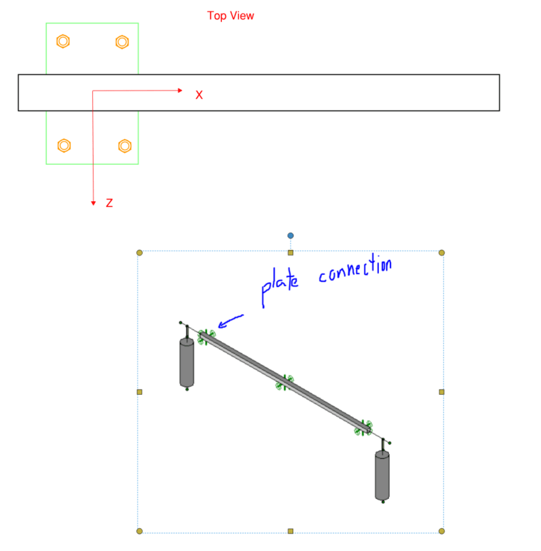
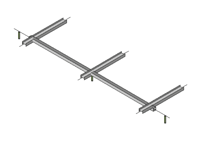
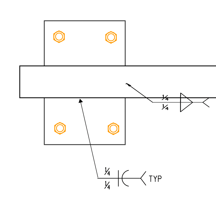
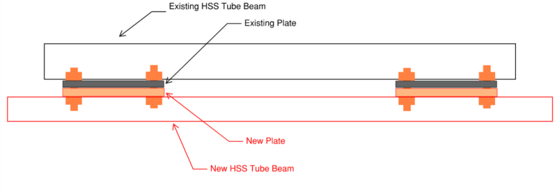
I want to install a new SQ tube beam under an existing beam by bolt connection. (Beam to plate connection is weld connection.)
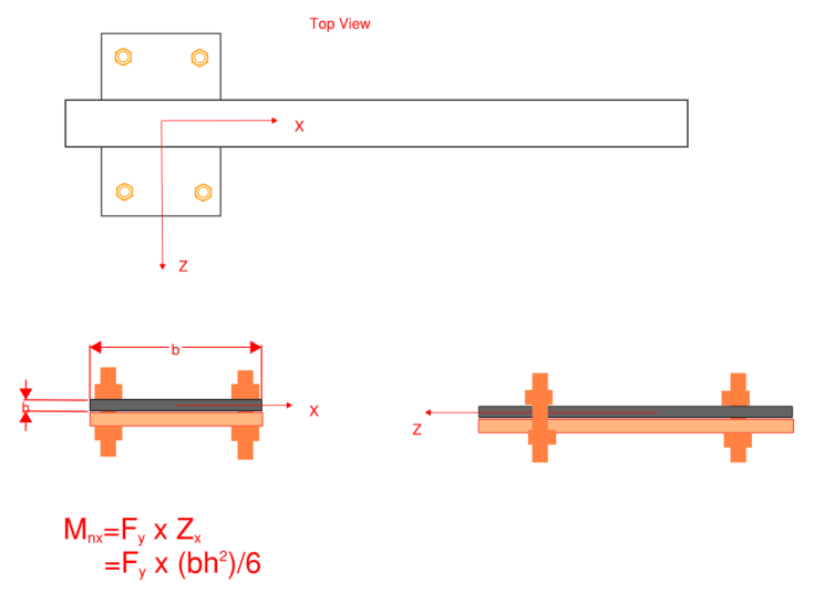
How should I determine the new plate thickness? Is considering plate tearing out from bolt enough?
I am quite concern about the moment force on the plate. How should I design it?


Thank you,
 
Replies continue below

Recommended for you

This could be simple, or it could be complex. If it's just hanging there with tension loads, you'll need to check prying in the plates. If there's shear, you'll have all of the typical checks for a bolted shear connection for both the bolts and the plate. Etc.

You have essentially zero details, so it's not possible to give you good guidance other than the need to discuss this with a senior engineer in your office.
 
Plate_Question_2_zvhm8d.png

It has some equipment hang under the new beam(show as round pipe in the picture). So it has bending moment around X and Z axis due to Wind load.

My question may sound stupid but I'm quite confused now.
Is it OK? if I just check the bending moment capacity around X axis on the plate like this.
If this is not correct, could you please suggest.
Plate_Question_3_tzcwqg.png


thank you everyone!


I saw this thread yesterday . With latest post of the OP , now i am more confused ..

Some questions ;

- Are the round pipes in the picture new equipment hang under the new beam ? And gravity direction is Y ?

- Are there three connections ?

- What about the supports of existing beam , and spans ?

Apparently the loads at Y direction and the primary moment would be Mz .


No!! not really...

Still the best approach could be the assumption of combined beam and calculate the shear values at plate joints for gravity load case..
It would be better to provide more details ..


I cannot give you the formula for success, but I can give you the formula for failure..It is: Try to please everybody.

 
HTURKAK said:
I saw this thread yesterday . With latest post of the OP , now i am more confused ..

Some questions ;

- Are the round pipes in the picture new equipment hang under the new beam ? And gravity direction is Y ?
Yes
- Are there three connections ?
Yes
- What about the supports of existing beam , and spans ?
The existing beam looks similar the structure in the link below.(I want to show the real photos but I am not sure that I can do it)
The owners just want me to design the new beam to increase the spacing between equipment and they assumed that the existing structure is adequate.

Plate_Question_4_pjk0so.png


Apparently the loads at Y direction and the primary moment would be Mz .

No!! not really...

Still the best approach could be the assumption of combined beam and calculate the shear values at plate joints for gravity load case..
It would be better to provide more details ..

Plate_Question_5_jsthgv.png

Here is a detail how the plate is connected to the square beam.

Thank you for every comment!
 
Status
Not open for further replies.
Back
Top