Continue to Site

Eng-Tips is the largest engineering community on the Internet

Intelligent Work Forums for Engineering Professionals

  • Congratulations KootK on being selected by the Eng-Tips community for having the most helpful posts in the forums last week. Way to Go!

How to accommodate large bearing rotations during construction?

Status
Not open for further replies.

bugbus

Structural
Aug 14, 2018
502
For composite steel bridges, the bearings undergo relatively large rotations during construction (i.e. the weight of wet concrete, any superimposed dead loads, creep and shrinkage in the deck).

For long spans, this rotation could be close to the rotation capacity of the bearing, e.g. ~0.015 radians for elastomeric bearings. This would leave no further ability to rotate and limits the allowable vertical loads on the bearings. In fact, it is a requirement in my local code that the faces of the elastomeric bearing are parallel at the completion of construction.

In my case, elastomeric bearings are really preferable because they keep the superstructure fairly well isolated seismically, which improves the design. Spherical bearings, while having a large rotation capacity, are probably not an option in this case because they will attract enormous earthquake forces which would have to be designed for.

I am wondering what options there would be to avoid over-rotating the elastomeric bearings during construction, such that they end up essentially at 'zero rotation' by the time construction has finished? I suppose using temporary bearings during construction and installing the permanent bearings after most of the rotation has occurred would be one option, but not sure how practical this is. Any other ideas?


 
Replies continue below

Recommended for you

gusmurr- I know nothing about bearings etc so can offer no help. Could you post a pic of the type of bearing you are discussing please. Id like to see them, curious to see how they rotate. Is the rotation you talk about from vertical I take it?

Thanks,
 
Beveled sole plates or shims are often used to accommodate profile grade and rotations due to dead load. These may be vulcanized to the elastomeric bearings or loose. The steel girders will not sit flat on the sole plates until all dead load deflection has occurred, so there are often gaps during erection prior to deck placement. There really isn't much the contractor can do about them other than trust that the EOR properly calculated the girder deflections for the steel self weight and the staged deck placement and then properly detailed the bearings and sole plates such that the gaps close up. Then the contractor can complete the bearing installation which often means simply welding the bearing sole plate to the girder flange. Since the bearings and girders don't really fit/work together until the end of construction, the contractor/erector has to provide other means of stability during erection and confirm that the bearings can accommodate being loaded on one edge during steel placement. Sometimes temporary blocking is used as an alternate support during erection. Another item to note is that the total dead load deflection can cause a thrusting action at the bearings similar to the movement caused by temperature changes. If the bearing has not been designed for this additional horizontal deflection, then the contractor may have to reset each bearings after construction but prior to opening the bridge.

The National Steel Bridge Alliance (NSBA) has a lot of great resources available for free. An updated version of the bearing document is coming out soon.

Also, time dependent effects usually are not explicitly included in most composite steel girder bridge design. It is accounted for in AASHTO by using "short term" and "long term" section properties.
 
I am still fairly fresh out of school so pardon me if I am wrong. I thought the steel girders are cambered so that when you first erect the girders your bearings are rotated the "opposite" way and once the dead loads and short-term time-dependent loads are added on, the girder deflects to the horizontal state and the bearings would have zero rotation?

I guess a potential (but more costly) solution would be to jack the bridge to reset the bearing.
 
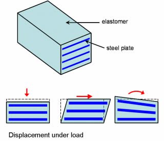
EireChch, for your info, see picture below. The rotation comes about by one side of the bearing compressing more than the other.

laminated-elastomeric-bearing-distribute-load_aiw5sr.jpg


jorton & kewli,
Thanks to you both. It seems obvious now that you mention it that the girder could be landed with existing rotation at the bearings so that it ends up flat by the time construction is completed.
 
kewli, you're correct that girders are cambered for dead and superimposed dead loads. However, the bearings usually won't rotate in the opposite direction when the girder first is placed; might bulge a little on the back side.


Elastomeric bearings "typically" won't over-rotate during deck placement. They might slide a little until the DL & SDL camber is released. The way to deal with that is to reposition them and then weld them to the girders after the deck is placed.

gusmurr - one thing you didn't mention is skew. If the skew is zero, all four corners of each bearing should deform vertically by the same amount. If you have a sharp skew, the deck placement can do funny things to the bearings depending on how the steel was erected -it could make things worse - and if the thermal design length didn't account for the skew.

A few years back I had to investigate bearing issues on a new bridge with 30-degree skew. The contractor erected the steel vertical and didn't run the finishing machine along the skew. The girders were out of plumb and numerous attempts at resetting the bearings were futile. It didn't help that the designer didn't account for the skew in the length used for thermal expansion.
 
Our designs would be similar to what kewli suggested, that the girder cambering should account for the final dead load rotation. Grade is accounted for by a beveled sole plate when needed.

Rod Smith, P.E., The artist formerly known as HotRod10
 
Agree with BridgeSmith. A good way to deal with rotation caused by grade is to use beveled sole plates.

As an interesting side note, yesterday I was visiting with a fabricator and asked why there were holes in the bottom flange at the end of the girder. A particular DOT requires the anchor rods to go through the bottom flange and not through the sole plate on each side of the girder. The problem was if the anchor bolts were preset, the end rotation of the girder due to dead load camber would not allow the anchor bolts to fit through the holes in the flange, even with oversized holes (the girder was 9 feet deep).

Don't ask me about the holes in the bearing pads for the anchor bolts. I seem to remember reading that was a bad thing.
 
Don't ask me about the holes in the bearing pads for the anchor bolts. I seem to remember reading that was a bad thing.

Three reasons we don't put holes or slots in bearing pads:

1) There's a reduction in the stiffness (shape factor) of the bearing pad that's a PITA to calculate,
2) the pads are more difficult to fabricate, and
3) If the anchor bolts go through the pad, it makes it a much more difficult process to replace the bearing pad.

Number 3 is the primary reason we don't put holes or slots in the bearing pads.

Rod Smith, P.E., The artist formerly known as HotRod10
 
Status
Not open for further replies.

Part and Inventory Search

Sponsor