I have a situation where my RCC structure is not exhibiting the desired behavior in ETABS due to the PT transfer beam at the first-floor roof level. Below are the details of the structure:
Number of Floors - G+4
Ground Floor Height - 3.2m (Parking)
First Floor Height - 6.2m (Mezzanine Floor at 3.2m) (Banquet Hall)
Second Floor Height - 3.6m (Accommodation)
Third Floor Height - 3.6m (Accommodation)
Fourth Floor Height - 3.6m (Accommodation)
Code - Indian
Framing Type - Ordinary
Type of Analysis - Equivalent Static Analysis
Importance Factor - 1.5
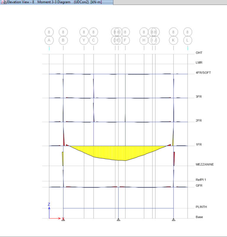
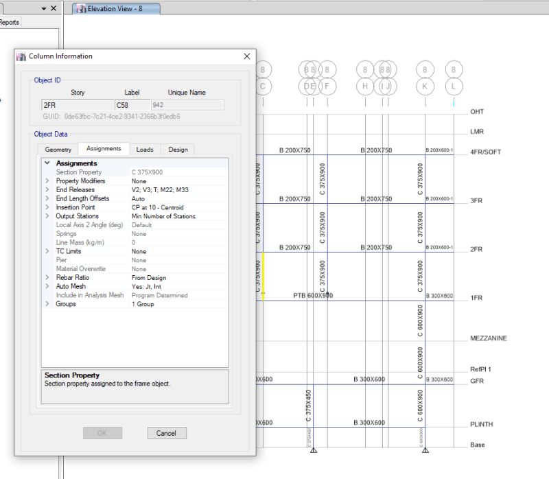
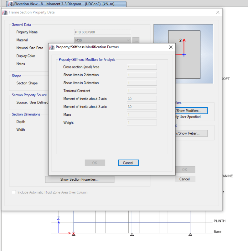
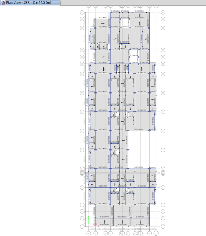
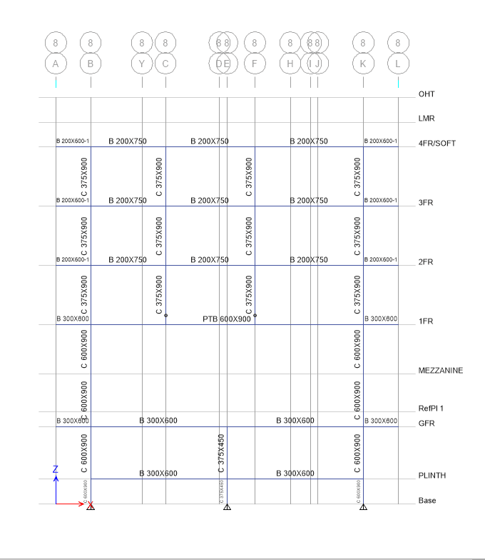
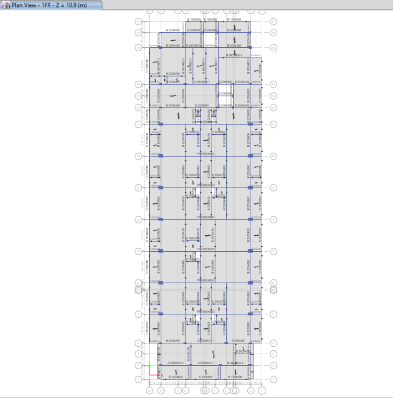
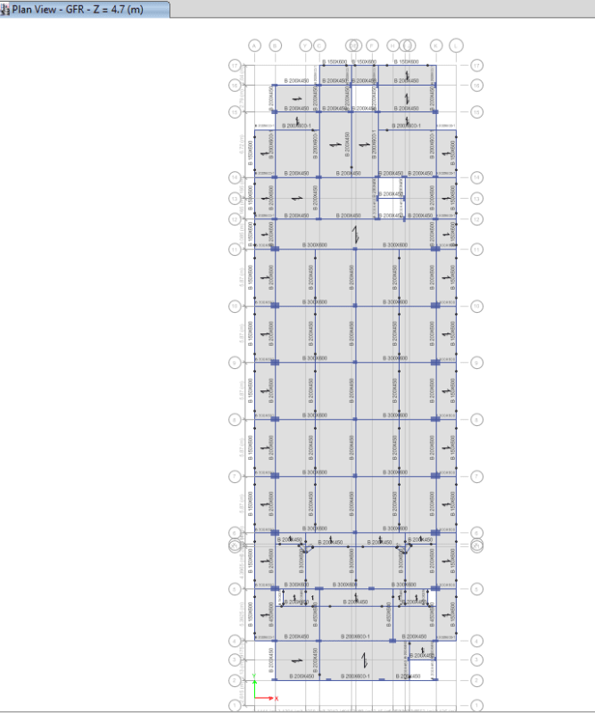
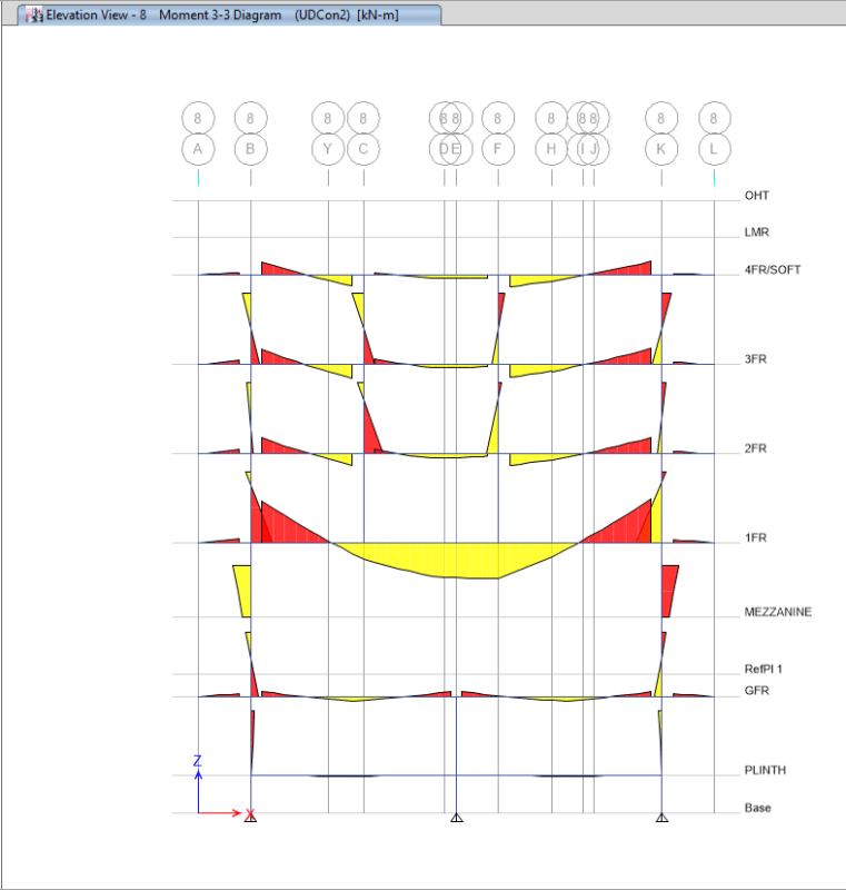
Since there is a banquet hall on the first floor, I cannot provide columns in the span of the building, which is 16.5m center to center. For the accommodation from the second floor level upwards, I raised stub columns from the second floor level from PT transfer beams (beams spanning 16.5m). I defined PT beams as normal RCC beams for the analysis purpose in ETABS; later on, PT beams will be designed separately. While modeling stub columns, I have released M22, M33, T, V2 & V3 at the base of stub columns.
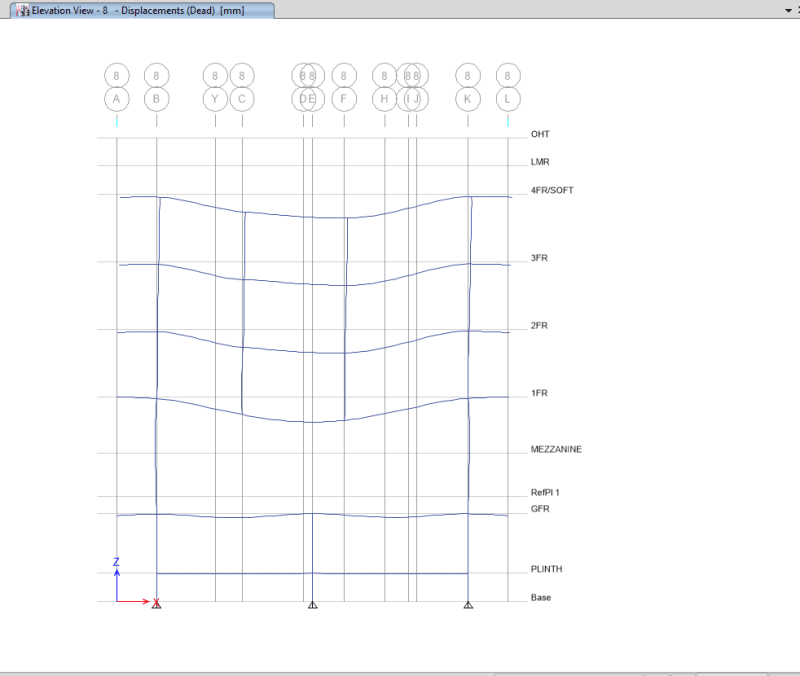
The problem is, as I defined PT beams as normal RCC beams, the deflection I am getting is more because of that the entire structure above those PT beams is not behaving as it is supposed to. I aim to restrict the long-term deflection of the PT beam to 17-18mm and short-term deflection to 7-8mm, but here in my model, I am getting around 60-75mm deflection for the gravity load combination.
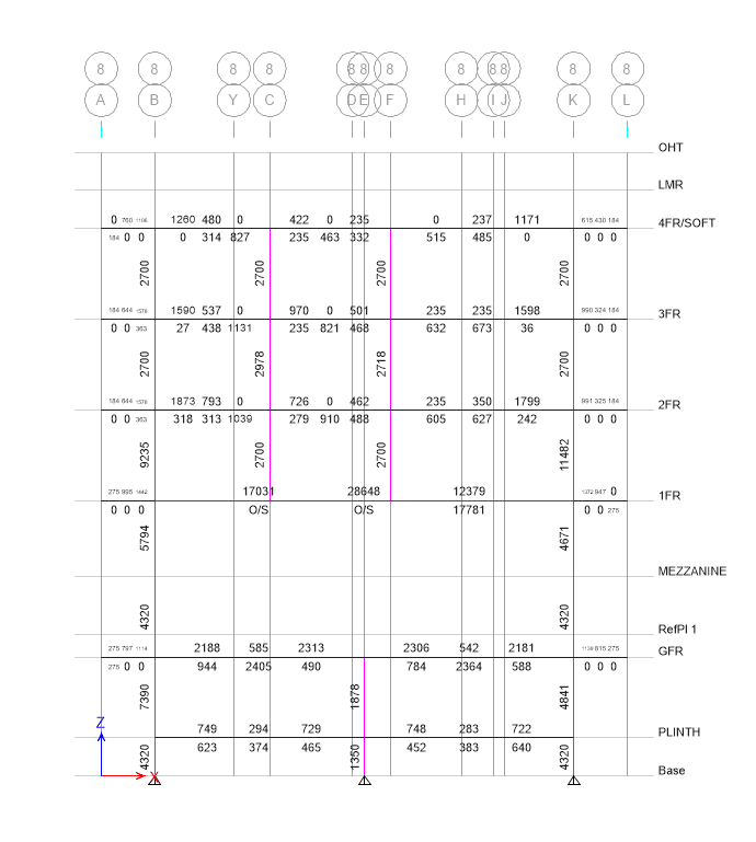
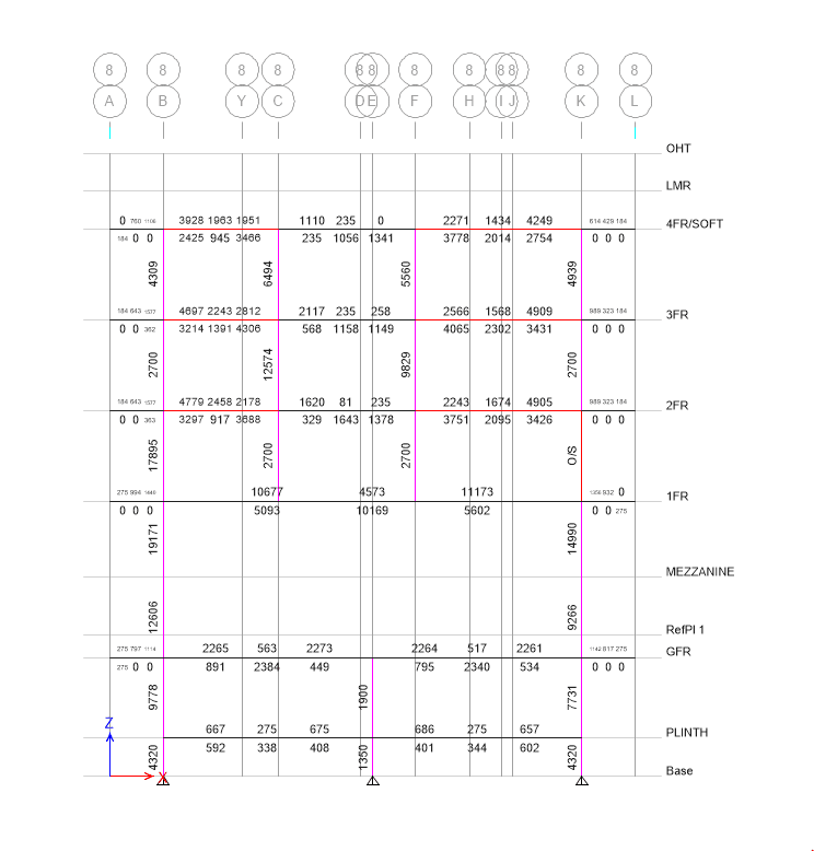
I tried to control the deflection of PT transfer beams by assigning hinge and roller support to the base of the stub column, but doing that reduced my column reinforcement considerably (from around 3.5% to 0.8%). I even tried assigning a point spring (restricting to 5mm deflection) to the base of the stub, but the result was the same. I want to know the right practice to model and analyze a structure that has PT transfer beams with stub columns on top and how to control the deflection of PT beams without affecting the column reinforcement.
I have attached a few screenshots and the ETABS model for reference. I am looking for a solution to this problem. Your comments are valuable and greatly appreciated. Thank you
Link


