FlameOfAnor
Student
Hi everyone
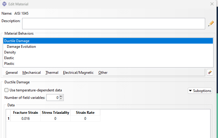
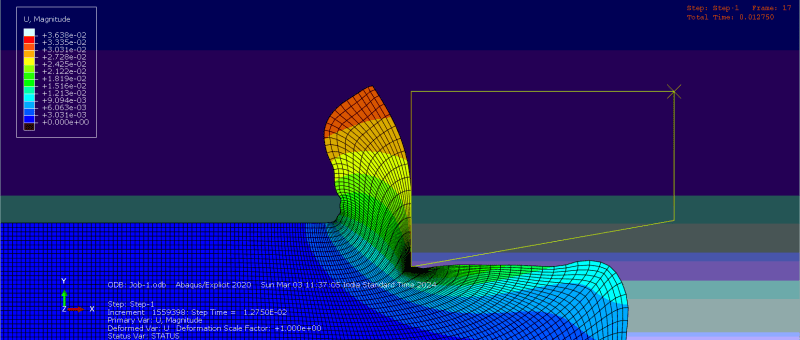
I want to simulate chip formation on machining in abaqus. I found a youtube video which did exactly the same. But in the video they used Johnson Cook damage model for element deletion as shown in the below screenshot.
[URL unfurl="true"]https://res.cloudinary.com/engineering-com/image/upload/v1708669315/tips/jcn97b4pwgjc1_ivfjha.webp[/url]
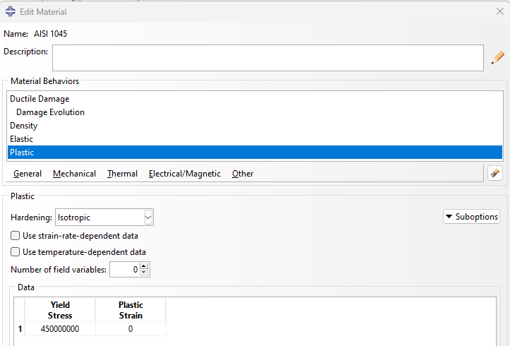
I was wondering if I could use just the yield stress as a element deletion criteria instead of using the JC model. The idea here the material gets strained only in the linear elastic region before the chip forms, that is the element deletes. I hope this would also make the simulation finish faster ( my understanding was that straining the material in plastic region is what leads to high time consumption, the simulation done by following the youtube video takes almost a day to finish). Since the simulation is for a demonstration purpose a very accurate picture of the chip formation is not needed.
Is this possible? Any help is appreciated.
I want to simulate chip formation on machining in abaqus. I found a youtube video which did exactly the same. But in the video they used Johnson Cook damage model for element deletion as shown in the below screenshot.
[URL unfurl="true"]https://res.cloudinary.com/engineering-com/image/upload/v1708669315/tips/jcn97b4pwgjc1_ivfjha.webp[/url]
I was wondering if I could use just the yield stress as a element deletion criteria instead of using the JC model. The idea here the material gets strained only in the linear elastic region before the chip forms, that is the element deletes. I hope this would also make the simulation finish faster ( my understanding was that straining the material in plastic region is what leads to high time consumption, the simulation done by following the youtube video takes almost a day to finish). Since the simulation is for a demonstration purpose a very accurate picture of the chip formation is not needed.
Is this possible? Any help is appreciated.