Continue to Site

Eng-Tips is the largest engineering community on the Internet

Intelligent Work Forums for Engineering Professionals

  • Congratulations KootK on being selected by the Eng-Tips community for having the most helpful posts in the forums last week. Way to Go!

How to adjust feature control frame position in SolidWorks

Status
Not open for further replies.

Joccob

Mechanical
Apr 22, 2021
7
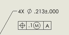
I'm using SolidWorkd 2023 and as shown in the image below, the continuous feature symbol is overlapping with the feature control frame, is there a way to adjust that?
Screenshot_2023-06-14_132528_mswxrg.png

Ideally I want it to look like this:
Screenshot_2023-06-14_132954_ekxr35.png
 
Replies continue below

Recommended for you

Yeah, it is attached to the dim, but for some reason, it does not auto-adjust based on the symbol ... I tried delete the FCF and reapply it, still the same.
 
I see the same problem. I have looked everywhere, can't find a fix. You may need to contact SolidWorks.

Chris, CSWP
SolidWorks
ctophers home
 
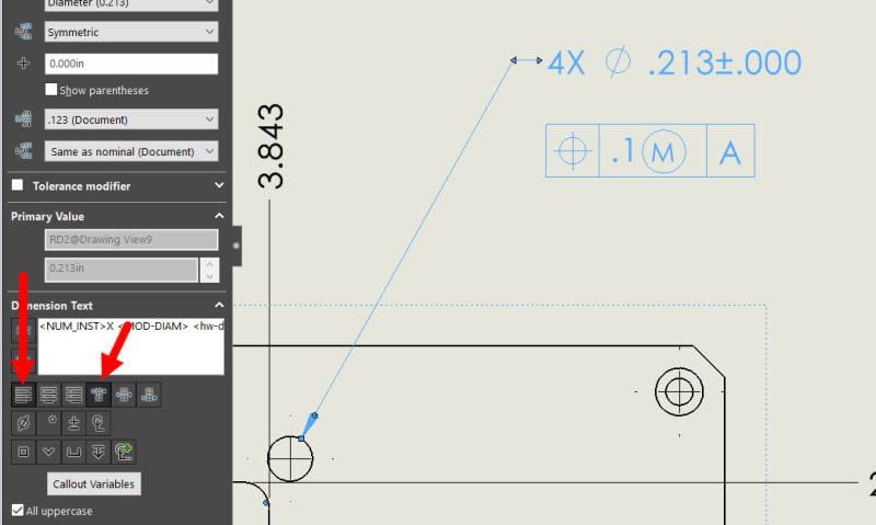
it's a little excessive, but you can edit the dimension, click enter and then the space bar and it does this:
GEO-Dim_qxbzmc.jpg


Also maybe if you use the Left justification on the dimension might help if your not using it already? Anytime I add dimensions I have go through and adjust them all to be Right\Left justified and Top Justified when required.

GEO-Dim2_semqek.jpg


Scott Baugh, CSWP [pc2]
Mechanical Engineer
Ciholas

"If it's not broke, Don't fix it!"
faq731-376
 
Hi, Joccob:

I just tied and I don't have this issue with mine. I use SW2022. I think it is related to your windows fonts (TTF font).

Best regards,

Alex
 
Thanks Jassco, but that's strange, I never really touch the default font of SW before (which is Century Gothic). What fonts are you using? Any thoughts on how to fix the font?
 
Fonts - something I know about - the problem looks like the software ignores the descender of the <CF> symbol, that is the part of the glyph that is below the baseline for the character. Whoever wrote this part of the layout knew enough to set the line spacing to avoid those for the dimensions, or assumed there weren't going to be descenders as digits and upper case English letters don't have them.

Note also that in the example the symbol border for <CF> is much tighter to the contents helped by the extra vertical space for the Feature Control Frame.

Overall it looks like a group effort among a bunch who don't talk to each other.
 
Hi, Joccob:

Characters with a boarder (elongated HEX) are a special font. It must be registered properly in Windows Systems folder during SW installation. Solidworks dialog boxes use TTF (True Type Font) fonts in the windows. These files have .TTF as extensions. Talk to your IT. They know how to install windows TTF fonts. It can be done in a single line command using Windows command prompt app. I don't remember exactly. But I used to do that. Please do a search on Goolge or Youtube on "how to install ttf fonts windows".

I'll let you know if I recall. I have a note somewhere.

Good luck!

Alex
 
Status
Not open for further replies.

Part and Inventory Search

Sponsor