Eng-Tips is the largest engineering community on the Internet

Intelligent Work Forums for Engineering Professionals

  • Congratulations waross on being selected by the Tek-Tips community for having the most helpful posts in the forums last week. Way to Go!

How to Attach Extra Wood to an Already Built Ridge Beam? 1

Status
Not open for further replies.

GaryHStr

Structural
Jul 12, 2022
8
0
0
GB
Hey everyone,

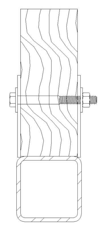
I'm working on a bit of a situation here. I've got a ridge beam in a building that's already up. It's about 9.5 inches by 3.5 inches and it's bending more than it should. I was thinking about adding a steel plate, but that won't work because it'll get in the way of the rafters.

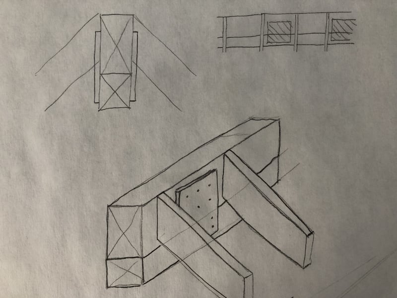
So, my plan now is to attach another piece of wood to the bottom of this beam. The new piece would be about 4 inches by 3 inches, making the whole beam around 12.4 inches deep.

The thing is, I'm not sure about the best way to attach this new piece of wood since the beam's already in place. Have any of you done something like this? What worked for you?

Appreciate your insights!
 
Replies continue below

Recommended for you

Thanks for your response! To clarify, there's no obvious deflection visibly present in the ridge beam. The concern about the beam's inadequacy is based on calculations rather than visible signs of distress. According to these calculations, the existing timber beam's size doesn't meet the required standards for strength and stiffness.

As for the structure, the ridge beam is resting on a king post frame. The roof is already constructed, and adding elements like collar ties would require significant alterations to the existing roof structure, which we're trying to avoid. We're looking for a solution that can reinforce the beam as it currently is, hence the idea of adding timber to the bottom of the existing ridge beam.

Looking forward to any further insights you might have!
 
What is the framing? Is the ridge beam an actual beam, or is it a compression element transferring the load from one rafter to the opposite one. Are there collar ties that take care of this compression load at the rafter beam? Need to know what the framing is... it has a big impact on deflectons, too.

-----*****-----
So strange to see the singularity approaching while the entire planet is rapidly turning into a hellscape. -John Coates

-Dik
 
Thanks for your interest in the details! The ridge beam in this structure is an actual beam, not just a compression element. It's designed to carry the load of the roof, and it is supported at each end by a king post frame. The ridge beam's primary role is to support the common rafters, which are connected to it.

Regarding the rest of the roof framing, there aren't any collar ties involved in this particular design. The roof structure primarily consists of the ridge beam, king post frame, and common rafters. The deflection concern arises from the calculations indicating that the current ridge beam's size isn’t sufficient to handle the loads as per the required standards, hence the need for reinforcement.

I hope this provides a clearer picture of the framing and the situation we're dealing with. Any further advice or insights would be greatly appreciated!
 
Attempting to lag bolt another wood piece to the bottom of the beam seems sketchy.
How about bolting a steel C channel to the bottom of the beam, with the bolts thru the full depth of the existing beam?
 
What is the span of the ridge beam? and the end support? Can you insert a small HSS beneath it?

-----*****-----
So strange to see the singularity approaching while the entire planet is rapidly turning into a hellscape. -John Coates

-Dik
 
The ridge beam spans about 16.4 feet and is supported by king posts at both ends. These king posts extend from the tie beam up to the ridge beam.
 
Can you do something like...

Clipboard01_bebxyz.jpg


-----*****-----
So strange to see the singularity approaching while the entire planet is rapidly turning into a hellscape. -John Coates

-Dik
 
Adding wood alone might not be enough. Consider sistering, steel straps, or internal reinforcement options with a pro. Building safety comes first
 

Thank you for the suggestion and the visual. It looks like a strong connection method. However, there's a bit of a snag with this approach. The position where the bolts would go through is exactly where the rafters meet the ridge beam. Any kind of bolted connection through the beam at that point would clash with the rafters, making this particular method unworkable for our situation.

I'm still on the lookout for a solution that reinforces the beam without affecting the existing rafters. If you have any other ideas that could navigate around the rafter positions, I'd be eager to hear them.

Thanks again for your input!
 
I don't think dik means the side plates to be continuous. The plates and bolts would go between the rafters. The solution would not form a composite member, but rather tie two separate members together. The relative stiffnesses of the steel and wood members would define the deflection picture.
 
If the math works out, you could do Dik's idea with a wood bottom member and plywood side plates to get the composite action needed.
I usually just slam another ridge under the existing if I have the room.
 
Could you use SDS screws, wood, and PL Premium per original idea? The screws mainly to develop clamp force. They could scribe a plywood to go over each side as well. Glue and screw the ply to each side. I assume you only have one beam to reinforce, and access is reasonable.
 
I would use a new beam of the same width as the existing and attach the two beams together with plywood gusset plates between rafters along both sides, perhaps at every other rafter.
Like this:
new_beam_below_existing_ridge_vdszva.jpg


The plywood spacing and attachment is based on resisting the horizontal shear force at the junction between the two pieces (to ensure both members act as one). Shear stress = VQ/Ib.
 

The bolts and BAR connections are every couple of feet.

Steel was chosen because of it's stiffness. To connect a small wood mem to the underside compositely, you will have a huge connection problem to develop the shear... else, adhesives can be used.


Thanks hokie... I should have noted that.

-----*****-----
So strange to see the singularity approaching while the entire planet is rapidly turning into a hellscape. -John Coates

-Dik
 
Dik said:
To connect a small wood mem to the underside compositely, you will have a huge connection problem to develop the shear... else, adhesives can be used.

It can usually be done with plywood side plates as I and others suggested.
 
agree... and a whole bunch of nails or adhesive... Your connection force would be the shear stress at the interface x 16 x 3.5, plus whatever effect the eccentricity of the plywood shear plates. glue works, and I've occasionally used this.

-----*****-----
So strange to see the singularity approaching while the entire planet is rapidly turning into a hellscape. -John Coates

-Dik
 
T_brace_vcq9n9.jpg


Flip it upside down and face nail?

If you want composite action, sure, you'll need a lot of nails, but if you just want to add the two stiffnesses you need to keep the the "brace" nailed to the existing for it's own weight. The upper piece should force the lower piece to follow the same deflected shape, if you want to go to that level, so the flatwise piece won't be as effective as the primary element probably, since you need to keep it narrow enough to avoid conflict with the rafters that slope downward. The ridge beam is supposed to be deeper than the rafter to start with.

I know everybody wants to talk about lag screws but they are supposed to have two different drill diameters made before they are installed.

Since the nails are in constant tension, maybe a structural screw would be a better choice.
 
Status
Not open for further replies.
Back
Top