Continue to Site

Eng-Tips is the largest engineering community on the Internet

Intelligent Work Forums for Engineering Professionals

  • Congratulations MintJulep on being selected by the Eng-Tips community for having the most helpful posts in the forums last week. Way to Go!

how to become a protection & control engineer?

Status
Not open for further replies.

quantum-link

Electrical
Oct 31, 2019
15
so any tips for someone who is wanting to become a protection and control engineer? I have worked for 13 years in the consulting firm (mostly petrochemicals and oil/gas) and recently moved to the utility/energy sector.

i already have experience with power systems studies (load flow, short circuit, motor starting) so I have some understanding of power systems. i had some experience with protective relaying studies but not actual relay setting or programming.

so my question - if i wanted to become a good P&C engineer, what path must I take? how should penetrate this field?

right now I am mostly working in the substation design (mostly layouts)
 
Replies continue below

Recommended for you

Find a P&C job and understand sequence networks. Places are so desperate for P&C engineers that just knowing the color of the various brands of relays is enough to separate you from the other candidates. If you want to really separate yourself, buy an SEL microprocessor relay off of Ebay and play with it. It will maybe cost you $60.
 
If you don't have it already, get Blackburn's Protective Relaying book and read through it. It will give you enough background to have the confidence to move forward. You'll need an understanding of symmetrical components, and basics of coordination. Figuring out relay SETTINGS is one thing, and figuring out the PROGRAMMING or configuration is something else.

Just assume you can figure it out and then dive in. Obviously, having someone to review your work is really helpful initially.
 
@dpc I am already reading this book right now. can you become a P&C engineer without ever setting relays? i mean having to program the relay itself. i've seen here in the office our P&C guy is mostly commenting on the documents done by our 3rd party design firms. he is not manually dealing and working with relays but mostly dealing on the theoretical aspect of it such as specifying what type of protection scheme must be used for which type of situation
 
Right - it's going to depend on how the work is done within your organization. I worked for consultants, and one day I was told to figure out the settings for a bunch of relays. I was too dumb to admit I hadn't done it before.

If this is complex transmission line distance relaying with over/underreaching schemes, breaker failure, etc, then you may need some guidance. Looking at existing systems and settings is always a good place to start. Also standards and customs will vary depending on industry and geographic location. But it's probably not as complicated as you think it is. Also, look over the breaker control diagrams (trip and close) as well as the three-line diagrams. That will help with understanding of what the relays are supposed to be doing. One of the best protection engineers I ever worked with refused to do configuration or programming of digital relays. He developed the protection settings. Someone else had to take care of the rest.
 
Utilities usually have a protection design philosophy that dumbs down the settings and makes sure that the relays are set similarly. You learn more about relaying doing industrial projects than utility projects because you have to develop your settings yourself. At a utility, you can literally put an excel spreadsheet together that will spit out the set points for you without requiring any great understand standing from the engineer to set the relays. The settings in transmission relaying is more complex but each utility I have seen sets each line segment with the same exact philosophy if possible. There are interesting issues that come up that you only see at high voltages but for the most part transmission relaying is very cookie cutter in comparison to industrial.

At a utility, after a year a fresh grad is settings line relaying by him or her self. Overseeing the installation of standard line panels. Setting standard relay settings files. The complicated part usually is in figuring out how to interconnect new microprocessor relaying with whatever is there that is mechanical. A new sub with all new relaying panels is fairly straight forward.
 
@DM61850 wow thanks for that info. i feel like I have way underestimated myself then. you guys gave me more confidence to push this thru. thanks a lot
 
I second the recommendation about getting a SEL on ebay to augment books and papers. If you are in the US, these are very popular items. I built my own lab/rack from ebay finds. There are various "old school" ways of making current, like a variac & resistor, that can add to the experience.
 
Commissioning relays is a useful skill, but whether you'd get to do that as a protection engineer is likely a lot more location and employer dependent.

At the utility I used to work for, the settings were developed by the engineers, but in almost all cases were not actually set in the relays themselves by the engineers, rather that was done by commissioning staff.
There are likely skills to be developed in using test kits and how to appropriately simulate specific faults in order to validate the relay settings and operation, but whether you'll be able to get involved in that is very much dependent on who you'd work for.

Its also dependent on who you work for as to what particular settings and arrangements you might need to look at. Not physically commissioning the relays doesn't not make you a protection engineer, there are likely opportunities out there regardless.

EDMS Australia
 
@thermionic1 how do you simulate faults and scenarios with these 2nd hand relays from ebay? can you hook them up to your laptop and run some scenarios? do you have to purchase SEL software for them to work?
 
@quantum-link

Testing a digital relay is really a combination of using the PC and some kind of voltage / current source. On a SEL the PC is used to program the relay, monitor the metering data, monitor element status and sometimes modify the logic to bring an element directly to a contact for sensing (fluke, test set, lamp, etc). There are some older Multilin (269?) motor relays that use the PC to set up internal simulations in the device without the use of an external AC source.

The SEL setting SW is free - it's called SEL 5030. You need to register with SEL with a company email address. If you look at manuals for early SEL relays (100 & 200 series), there are fairly explicit instructions on how to set up a test. The SEL SW has a built in terminal - which is key to understanding SEL relays. In old programming terms, one can peek and poke into the relay and assign specific relay or logic elements to an output and also monitor the state of internal bits. Incredibly handy for troubleshooting and commissioning.

Old GE & Westinghouse/ABB electromechanical relay manuals(IAC 53/CO-9) give suggestions on how to make a current source circuit. Basically a variac ($50-75 on ebay) & power resistor (again ebay), and an ammeter. A small control transformer can also be shorted on the secondary and have the primary voltage adjusted from a variac for similar results. Since you are in charge of what the settings are, keep the current levels (pickup) low, so you can run through a fluke and don't need to worry about burning things up (another lesson altogether in testing relays :))

Every SEL has an SER feature. Program it appropriately and use that to verify times (SEL goes into detail about this in testing section). You will need a USB to serial (db9) adaptor and a db9 null modem adaptor. SEL sells a cable that does all of this on one for about $75 or amazon / ebay for much less.

Up until about 25 years ago, many relays both EM and Static / digital could be tested with this method or some derivation of. There is even a SEL application note about using a Weller soldering gun to test SEL recloser controllers!

With this basic setup you can test 50/51, 27/59 elements. With a single phase source, you can test Ph-Ph and Ph-N elements. The basic tests for these elements are pick up and timing. Pick up for a 50 element is performed by slowly ramping up the current unit it is sensed (fluke, lamp, SEL LED, etc). Timing for a 50 is zero to above the setting. 51 and some 27/59 elements make have an inverse characteristic which is normally tested at 2-3 points on the inverse characteristic. SEL provides graphs and the equations in the book. Make an excel sheet to plot the time curves. The old EM books will show a double pole, single throw switch used both to initiate the AC source and start a timer. I imagine if you are handy, an Audrio can be programmed to time and display for a few dollars. Else ebay may have something cheap.

Ebay currently has a SEL 251 for $70. Perfect for what you may want. (the link was a mess to paste). There are some SEl-221F's which could also be used, but don't expect to test distance elements with a simple set up. The unit can be powered from 120VAC (or 125 DC), so cut up a 3 prong cord, fuse the hot and you have power. I made a small 125VDC power supply from a DC/DC converter for about $20, for the logic inputs.

SEL Manuals are free to download as well, once registered. SEL is also very generous with loaner relays. I have 2 units on long term loan for an IEC-61850 lab I built at the office.

One other thing that can be appreciated from this exercise is some of the dangers of the older methods and advantages of modern test equipment that provides 4-6 voltages and 6 currents, with test SW that can automate many tasks, play back COMTRADE (fault) records, play back defined sequences (from Aspen, Cape, etc) and trigger the starting of 2 test sets separated by miles (remote station) via GPS for End to End testing of transmission protection schemes.

Hop this helps!

 
@quantum_link

It is easy to test the overcurrent elements with a resistor and 120v outlet voltage. They pickup on overcurrent and unless you are including directionality, you don't care about the phasing of the voltage.

The part that would require a little bit of thought is how to change the angle of the voltage with respect to the current. You can do this by putting together RLC circuits. You'll manage but it will just be a little bit more work. Faults are usually very inductive so you are probably set if you just use a big inductor to get the current to lag or lead (flip polarity of the connections) by 90 degrees. SEL relays are made to handle 100 A secondary so you need Xl = 2*pi*f to be in the range of a few ohms.

You might want to contact one of SEL's local office and ask if you can borrow a SEL-4000 Relay Test System. It is not a true voltage and current test set. It is a system that feeds the voltage and current measurements directly into the relay's memory through a ribbon cable. They sell them new for like $4,700 so it is nothing like a $60,000 Omicron digital test set. With the SEL-4000, you can feed comtrade voltage and currents in to the relays memory itself. It is not really something you would test the relay with but it lets you play with the relay without needing a $45-60k test set. They tried to sell them but no one wants them because you can't use them to test the relay with actual voltages and currents. They let me borrow one when I was trying to track down something cheap that could feed comtrade voltages and currents to a relay for a paper on ct saturation.

You probably put a relay through its paces with 61850 and SV (sample values) if you can figure it out. I think you might be able to feed voltages and currents to a relay with just a laptop hooked up to a network. I don't know how to set that up but I believe you could do it but you would have to tackle 61850 at the same time and that would be a lot.
 
@DM61850

i see, so i really have to hook up an account current and voltage source to the inputs of the relay and not just a software simulation
 
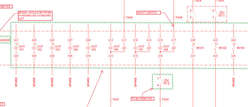
I appreciate you guys respond to my questions. i'll take this up further. another area where i need more improvement is the logic part of the relay. here is one of the projects we are working on. how can i learn how to pinpoint and comment on this drawing and say, this need change that needs to be this, etc
1112222_pujduo.png
 
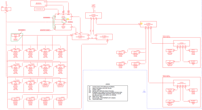
here is another drawing. I kinda understand the logic when it's explained to me that this relay is connected to that relay and they all are interconnected. but how can I reach an understanding that this specific arrangement is correct or not? and if some items or parts or signals is missing, i must be able to point that out. where should i begin to study the architecture of this?

45451656_coiysm.png
 

In the 1st drawing, the FT cut-out is on the more negative side of the relay, while others are on the more positive side. This is a client preference / standard. As an example, some users prefer to isolate both sides of the contact for ease of testing, which requires 2 blades - one on either side of the contact. This, by the way, makes testing safer as a test paddle (ABB FT) can be inserted and tested with the relay test set with wet contacts. Also useful if there is not a ground referenced DC supply. I suspect in this case the test switch on the more negative side is a relay fail contact to SCADA. If OUT101-106 were used for something, one might argue that the test SW on the (+) side is useless for testing. Ex. When the SW is on (-) side and SW is open, a Voltmeter can measure contact state with respect to ground on the jaw side- if the contact is closed, Fluke would read (+~65VDC on 125VDC system). If Out101 is a trip contact and breaker is closed, ~-65VDC would be measured on blade side -up from NEG rail, through CB Trip Coil and 52a. If that SW is closed, the CB would trip.

The second drawing is a communications overview. I can't zoom enough read details. It may be SCADA related, or if its IEC61850 based, thats past the 101 series of P&C lessons for today :)

Someone mentioned earlier that getting out in the field would be useful. I second that recommendation as there are many things not intuitively obvious from a piece of paper that can be learned working on a live system.

Working in a Utility environment is quite different from industrial or similar. As an example, in a Utility, hold cards may be legally used to prevent the operation of a device. It's quite simple - operate a breaker that has a hold card and you will never work there again (or other severe consequences). The System Operator or dispatcher has control and gives orders. It's a well thought out process and everyone is trained on these rules, often annually. In industrial or similar environment, LOTO applies and locks are placed on switching devices. The keys for the locks are locked.
 
@thermionic1

thanks. for drawing 1,would someone be able to learn this by self study? if so, are there courses out there that might help to speed up learning the inner workings of a relay? and the network connections, how the architecture of relay interconnection with SCADA usually is arranged. things like this.

yes, we do use iec81850.

does advanced courses on control systems teach these principles? I am looking at pursuing a master degree with some focus on electronics and Communications.
 
@quantum-link

It's entirely possible to learn through self study, or perhaps as mentioned above being assigned a project that's way above your ability or comfort level. I took a job with a company 21 years ago with a communications degree (mV, mW) and got thrown into the bears den "marking up drawings", which was really retrofitting digital relays in place of electro-mechanicals. I had never seen a single line drawing, a three line drawing or DC control schematics for a utility MV swgr. It was incredibly stressful as my work was started by a previous employee, there were deadlines and the guys in the shop couldn't start their work unit mine was complete.

Again, mentioned previously, modern digital relay design is much simpler from a DC control / wiring perspective. I would see if you could hunt down old Electro Mechanical control schematics for transmission line protection. Since the devices were discrete, there's a lot more going on in terms for not only tripping, but fault detectors, zone timers, blocking/steering diodes, reclose initiate, block reclose, breaker failure initiation, preventing reclose from a SCADA or local open, etc.

SEL relays are very popular in the US (you may have notices). SEL offers a variety of classes, both centered on their relays and some other topics. They also have a ton of literature available on their website. I'd recommend starting there as many of the classes are reasonably priced, meaning your employer is likely to not balk at the cost. Some are in Pullman, and others are held regionally.

Again, mentioned by others, but working in the field, like for a testing company, gives a lot of exposure very quickly. I would be sure not to hire on with a company that doesn't have several senior employees that can mentor you. On the utility side of things, there are plenty of testing companies / engineering firms doing this kind of work. Utilities are always doing something - new stations, upgrading old stations, repairs, modifications. It's a great opportunity to see a new relay panel being installed, replacing a 40 year old panel. That gives the opportunity to see the schematics from old and new and how so much of the functionality resides within the digital relay.

I work for an Engineering firm with about 200 employees. I don't know one person with a Masters degree in engineering. I do know 30-50+ people with a Professional Engineering Licence. The PE is strongly encouraged for all incoming engineers. There are many at my firm that got their PE while working for a Utility in a previous job, who freely admit that was the easy path. For the younger guys, there are study groups and time off is allotted for PR training classes. We have employees with MBA's, and Masters degrees in other fields, but I don't run into many that have MS EE on their business cards.

Networking relays and such is not terribly difficult. There are maybe 4 different communications mediums used. Some are point to point (plug relay into communications processor with serial cable), some are multi drop (plug a string of relays into a communication processor / plc), some are point to point fiber, some are ethernet based, so plug the relay into a switch / router. There is a network security side of things that may or may not be handled by IT. Often there is a redundant path for mission critical communications such as Transmission protection (Power Line Carrier + Fiber or ??) or in the station, such as your 61850 network diagram. BTW, all of this is very easy if it works.. It's the troubleshooting where you tend to learn things.

The inner workings of a relay are SW and HW. From the HW side a digital relay has a few components -A/D converters (VT/CT to 1001001), Opto Isolated inputs, CPU, memory, Output contact drivers. Some relays have more I/O, more A/D, more LEDs & pushbuttons, etc. The inner workings of the SW algorithms may be described in OEM technical papers or the instruction manual. Get that SEL relay from ebay and take it apart. You'll likely be able to identify many of these components yourself.

I'm currently mentoring a colleague, with 4 years in the field. His one weakness is his inability to take the relay test set home with him over the weekend and play around with the SEL-321 he has. He has been to several classes, but then complains that when faced with testing a relay it has been too long since his training. What does that say about him or the training?

Again, mentioned earlier - the industry is begging for competent P&C engineers.
 
How bad is the shortage of P&C engineers? And what is wrong with those coming in/doing it now since you mention competence? Just curious.
 
A big problem is that a mid-career engineer that finds an interest protection but has no relevant experience can’t get a protection job at a salary their total years of experience would suggest. You pretty much either have to start out in protection or edge into it slowly. I took the edge in sideways path. Started in a consulting firm doing building power systems and grabbed all the study work and MV system work I could. That eventually produced a working relationship with the protection group at the utility I presently work for. Between there and here I put in a stint as an application engineer for one of the relay manufacturers. I had no transmission experience, they had no transmission relays, it was a good fit. After some time there the utility had a distribution protection opening and they hired me. Been doing transmission protection much of the time since. Today I’m not doing hardly any new settings, my focus is operations, planning of new protection systems, and maintaining the system model.

Could never have been hired into a transmission protection position at the time, but with feet in the door there were plenty of opportunities to try new things.

Gotta give someone a reason to bring you in close to where you want to be and then volunteer for assignments that move you ever closer to the goal. May take a while.
 
Status
Not open for further replies.

Part and Inventory Search

Sponsor