Eng-Tips is the largest engineering community on the Internet

Intelligent Work Forums for Engineering Professionals

  • Congratulations waross on being selected by the Tek-Tips community for having the most helpful posts in the forums last week. Way to Go!

How to best model Shell intersections, recommendations?

Status
Not open for further replies.

donrafa7

Mechanical
Mar 13, 2015
13
0
0
US
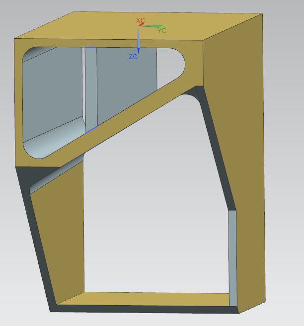
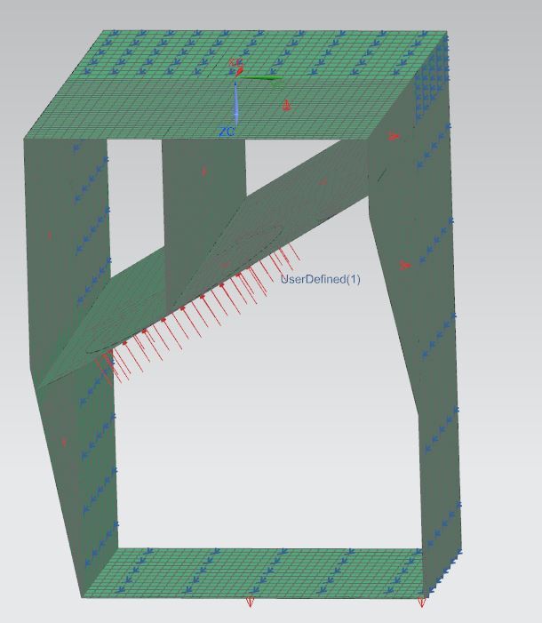
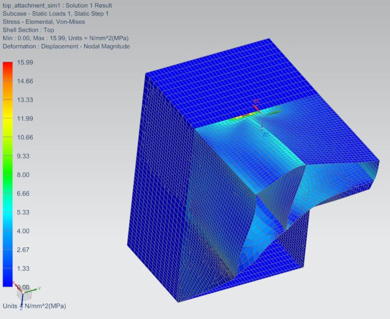
I am modeling a boxed item as shown in attached JPegs. I analyzed using shell elements and am getting high loads specifically at the T intersection shown. Item is bonded in place around all 4 faces so i put a fixed constraint at these locations. Is there a better way to analyze the problem, Maybe just do solid mesh and ensure at lease 3 elements at all thicknesses?
Capture1_cloevy.jpg
Capture3_zihumz.jpg
Capture4_mxhymp.jpg
 
Replies continue below

Recommended for you

You may get some advantage in using 3D elements as you won't be able to capture the stiffness of the filleted corners with shell elements, but I doubt it'd make much difference. Use quadrilateral elements if you're only using 3 elements through the thickness. In addition, if the square box section is fully restrained then why include it in the model? Just restrain the edges of the remaining section.

 
Lots of articles have been written on the use and drawbacks of "plate elements". Since there is no inherent thickness to the surfaces used in plate models there is no way the stress distribution at a "junction" can be accurate. This is the reason for the use of "Junction Rings" when plate models are used to evaluate nozzles/pressure vessels. It looks like your part is relatively small and 3D or brick elements would be the way to go. Since you're aware of the 3-element through the thickness concept I'm assuming you are investigating membrane stresses ? Of course you will have to linearize the brick model to get the membrane (the only advantage other than run time that plate elements provide).
 
Status
Not open for further replies.
Back
Top