Continue to Site

Eng-Tips is the largest engineering community on the Internet

Intelligent Work Forums for Engineering Professionals

  • Congratulations KootK on being selected by the Eng-Tips community for having the most helpful posts in the forums last week. Way to Go!

How to Break Leader Lines over Geometry?

Status
Not open for further replies.

Jake Omaha

Mechanical
Jun 9, 2023
5
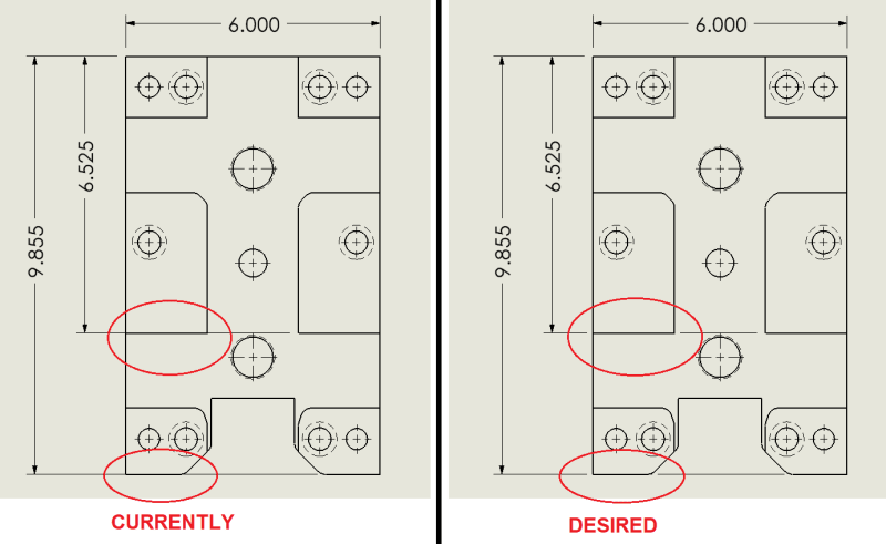
I need to break the leader lines of dimensions over geometry. I know there is the break lines button in the property manager but that only breaks a leader when it intersects another leader. Any help is appreciated. See pics of what I have and what I want. Thanks.
 
 https://files.engineering.com/getfile.aspx?folder=39befeeb-7f61-4147-b8ee-96aa2940f9f2&file=Leader.png
Replies continue below

Recommended for you

sw_gap_w2bvpr.png


Chris, CSWP
SolidWorks
ctophers home
 
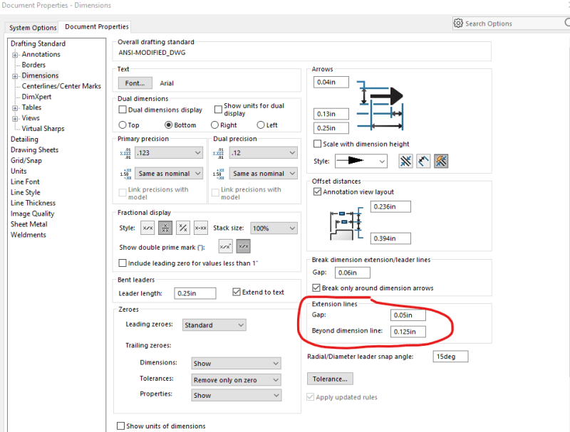
@ctopher. The extension lines gap and 'beyond dimension line' were both .05 before and I adjusted the 'beyond dimension line' to .125. Didn't do anything for me.
 
Hi, Jake:

No. Gaps of extension lines are automatic. You just need to pick correct entities (edges) to place your dimension.

Best regards,

Alex
 
Hi, Jake:

If those two dimensions apply to multiple features, you can add CF symbol to indicate them as continuous features. If they are not CF features, you can add "2X" (less quotation marks) to the dimensions and attach them to the features on the left.

Best regards,

Alex
 
@ctopher Restarting solidworks makes no difference.

@jassco I could do the 2X or CF note but I prefer to have a broken leader line. It was really easy to do in ProE
 
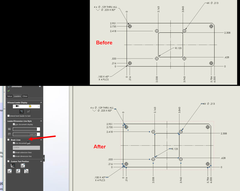
you have to make sure the option is on under your dimensions as well. it's not automatic.

I turn on the filter to select all my dimensions and then turn on the Break Line option.

Break_Dims_zqn82g.jpg


Scott Baugh, CSWP [pc2]
Mechanical Engineer
Ciholas

"If it's not broke, Don't fix it!"
faq731-376
 
Scott, I can break leaders that intersect each other fine, what I want to do is break leaders that intersect the model geometry on the print.

Leader_g1bxat.png
 
Hi, Jake:

That does not seem doable.

Your dimensions (both 6.525 and 9.855) are objects (DAO) in Solidworks. And the extension lines are children objects in the dimensions. These two objects are only related to their parent objects which are the edges that you applied the dimensions to. The extension lines have no relationship with the edges which they run over.

Best regards,

Alex
 
Not doable, you should have selected the closest edge to and the dimension line would not intersect the geometry. To make it work you will have to add construction sketch geometry if you absolutely need it look like that. For my drawings unless its dimensioned to that line its assumed to be the same dimension. Assuming can be bad, but I prefer Ordinate over linear its so much cleaner than linear and if the same is true, if there is no dimension to that line its the same Dim for both lines.

Scott Baugh, CSWP [pc2]
Mechanical Engineer
Ciholas

"If it's not broke, Don't fix it!"
faq731-376
 
Bummer I was hoping there might be away. If I were only to dimension the closest edge I would put a typical or similar note so there is no assumption necessary. On ProEngineer at my last job there was an easy way of breaking the lines how I want, guess solidworks has a little catching up to do.
 
Status
Not open for further replies.

Part and Inventory Search

Sponsor