Continue to Site

Eng-Tips is the largest engineering community on the Internet

Intelligent Work Forums for Engineering Professionals

  • Congratulations IDS on being selected by the Eng-Tips community for having the most helpful posts in the forums last week. Way to Go!

How to calculate required motor HP 8

Status
Not open for further replies.

PaulKraemer

Electrical
Jan 13, 2012
145
Hi,

I have an application in which I will be driving an 8" diameter roll that will be supported on each side by steel frames with fixed position precision bearings. I will be using a VFD to drive an AC motor with a 60:1 gearbox and an additional 2:1 belt/pulley reduction. Other than having to turn the roll itself at a constant speed, there is no additional load. From past experience, I feel pretty confident that a 1/2 HP motor will be able to do this job.

I'd like to know what calculations I can do based on the information above (and any other information I can request from the motor, gearbox, roll, and bearing manufacturers) that would allow me to determine with a higher level of confidence whether the 1/2 HP motor I have in mind will in fact work for this application.

Any advice will be greatly appreciated. Thanks in advance.

Paul


Replies continue below

Recommended for you

Probably the largest single load will be the friction of the V belts in the pulleys.
If this is between the motor and the gearbox the losses will be much greater than if the belt is between the gearbox and the roller.
Churning the grease in the gearbox may be a load.
Do some Googling to try to find out how much the belts will lose to side friction in the pulleys.
Google again to look for gearbox losses at no load. (Or with the belt load.)
Be aware of any possible binding or side thrust on the bearings.


Bill
--------------------
"Why not the best?"
Jimmy Carter
 
Hi Bill,

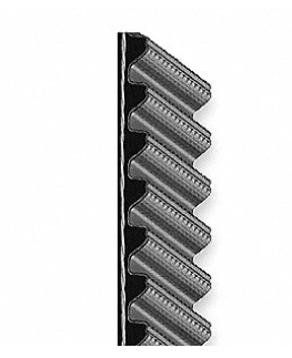
Thank you for your response. Our gearbox will be directly coupled to the motor. The belt will be between the gearbox and the roller. I am pretty ignorant with regard to types of belts as I work in the electrical field more than mechanical, but the belts we used are described as timing belts. I am pretty sure we always use 8 mm pitch in various lengths. A typical part number we use would be "8M-1440-20 HTD TIMING BELT". I have attached an image below...

TimingBelt_bltna5.png


I will google as you suggested. I am just wondering if you would think this kind of belt would introduce more or less loss that a typical "V-Belt" (if in fact there is a difference between what we use and what you had in mind).

thanks again - I really appreciate your help.

Best regards,
Paul
 
That's a timing belt - has a fairly precise positional relationship between drive and driven pulleys but not desperately efficient. Google 'Poly-Vee' belts for one relatively low-loss belt type.
 
I will assume a motor synchronous speed of 1800 RPM. That is the most common speed of three phase induction motors in North America. (Another assumption, almost.)
That will put your output shaft at 30 RPM.
A little belt friction at that reduction will be almost negligible at the motor.
Not a bad choice at that speed and reduction, but check out Scotty's lead as well.
Timing belts like to run tight.
Consider a strong spring loaded idler near the smaller pulley if you decide on the timing belt.


Bill
--------------------
"Why not the best?"
Jimmy Carter
 
Hi Bill and ScottyUK,

Thank you for your responses and I apologize I took so long to follow up. Bill, you are correct to assume a motor synchronous speed of 1800 RPM. With my planned 60:1 gearbox, this would make the top speed of my driven roll 30 RPM, as you mentioned. I can do some googling as you suggested to come up with an estimate for belt/pulley losses and for gearbox losses, but if I ignore these losses for now, I'd really like to know how to calculate the HP required to drive my 8 inch diameter roll (assuming lossless gearbox and belt/pulleys).

I assume I will need to know the weight of my 8 inch diameter roll. Is there any other information I will need to do this calculation?

Thanks again,
Paul


Assuming lossless belts/pulleys/gearboxes/bearings then you will require 0HP to turn the roller at a constant speed. So, those are pointless assumptions to make.

I suggest you also look at the acceleration and deceleration requirements.
 
Hi Bill, Keith, and Lionel,

Thank you for your responses. This is an 8 inch diameter, 12 inch wide steel roll of hollow construction as shown in the following drawing. While the hollow 8 inch diameter part is 12 inches wide, the roll does have smaller diameter, solid shafts on each side that allow it to be supported by bearings mounted in front and rear support frames. The longer shaft is used to couple the roll to my drive system.

8-inch-dia-roll_gbfdme.png


The article that Bill mentioned was very helpful. I do not have this roll in house yet, but I will be able to weigh it when I do. As my roll does not exactly match the description of a hollow or solid cylinder, I suppose I will have to estimate the radius of gyration, but the formula in the article will allow me to estimate my required acceleration torque.

(I do not require fast acceleration - I'd say if I can get the roll up to 20 rpm in 5 seconds, that would be great. After the initial acceleration, normal operation would be running at a constant speed for an extended time and then stopping).

If I use this method to calculate/estimate my required acceleration torque, the next thing I would like to do is learn how to relate this to required motor horsepower.

According to the engineering information presented in a Martin Sprocket and Gear catalog, the formula for HP is :

HP = Torque (in lb-ft) * RPM / 5252

... If I use the formula in the article mentioned by Bill to calculate my required acceleration torque, and plug it in to the HP formula above, I suppose this might give me a clue regarding my required motor HP if the motor was going to drive the Roll directly, but I am not sure how this is complicated by the fact that I will be using a 60:1 gearbox.

If any of you guys can give me a clue what information I need about my 60:1 gearbox in order to determine how this will affect my required motor HP, I would greatly appreciate it.

Thanks again for all your help.

Best regards,
Paul
 
Acklands-Grainger offers a gearmotor with a 30:1 reduction driven by a 1/15 HP motor.
You are belt driving and the belt will have more friction than the direct drive.
Seat of the pants and a WAG I suggest a 1/4 HP motor and move on.
1/4 HP motors are often used to belt drive fans and your greatest loss will be belt friction.
Your won't have much inertia at 30 RPM.

Bill
--------------------
"Why not the best?"
Jimmy Carter
 
The power to accelerate and and rotate the roll will be close to zero. What is the purpose of the roll that would require work? Why not make it an idler roll with no motor?
 
pffft!

I concur with Bill and Comp. That will take nothing to turn.

I'd make every effort to directly drive it with a 1/4hp motor and run it with a VFD. Probably $50 VFD will let you set it at between 10 and 1725RPM.

If this thing is actually going to do something like move a conveyor then it and it's bearings at 20RPM is still so little as to be completely negligible. The only thing you need to compute is the tension and hence work that roller will have to impart on the driven belt of whatever it's tasked with moving.

In that case then yeah a drive reduction would be in order. Do it with only a belt and a VFD.

Keith Cress
kcress -
 
Hi Bill, Comp, and Keith,

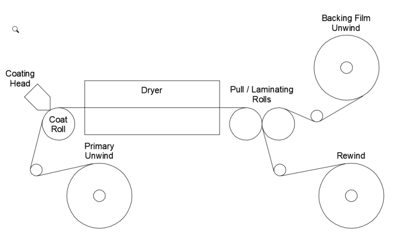
To give you a better idea of my entire process, the 8 inch diameter roll I have described in previous posts is the one that I have labeled "Coat Roll" on the following illustration. The entire machine/process will take a spool of flat material (typically a 0.003" thick poly film) and will unwind it at constant speed. As it is being unwound, it will pass underneath a coating head that will apply a thin (adhesive based) coating to the film before the film is passed through a dryer. After the Dryer, the coated film passes through a pair of "Pull/Laminating" Rolls where a backing film is applied on top of the coating. After the Pull/Laminating Rolls, the three layer finished product (two films with a coating in between) is wound up at at a Rewind.
WebPath_hshlsl.png


The Pull Rolls determine the speed at which the film is conveyed through the machine. The Pull Roll on the left is chrome-plated steel, mounted in fixed position bearings, and directly driven. The Pull Roll on the right is silicone covered and mounted in pneumatically actuated swingarms. The Silicone Covered roll is not directly driven - it is driven only by making surface contact with the chrome-plated Pull Roll (or the three layer finished product). By setting the gap (Nip) between the Pull Rolls properly, the Pull Rolls provide the necessary traction to pull the films at a constant speed (the surface speed at which we drive the Chrome-Plated Pull Roll).

In this scenario, the Coat Roll is chrome-plated. We have tried making this an idler in the past, but found that the film did not provide enough traction to make it turn reliably. Having the film slide over the Coat Roll without it turning generated static electricity, which lead to some issues. This is why we typically drive the Coat Roll now at the same surface speed as the Pull Rolls (and the speed of the film), just not to create drag.

Based on what you have said, it seems as though the HP required of my Coat Roll drive will be very small. We have been building this type of machine for many years, and we have always used gearboxes rather than directly driving our rolls. I think our original reasoning was that (due to required drying time), we run these machines very slowly. Back in the days of DC motors, we used 20:1 as a rule-of-thumb speed range as far as what you can hope to get out of a DC motor without worrying about cogging (although in actual experience, I have had reasonably good results up to 50:1).

I assume the HP required of my Chrome-Plated Pull Roll will be higher than that required for my Coat Roll because the Pull Roll has to create the force that pulls the films through the machine (against the resistance created by the Primary Unwind and the Backing Film Unwind, for which we use electro-magnetic brakes to create our desired level of tension.

The reason I started out only by describing my Coat Roll in my question is because this is the simplest of my drive systems. I figured that if I could learn how to calculate my required motor HP (assuming a 60:1 gearbox), I could get a feel for the basics before digging in to the more complicated scenarios of the Pull Roll drive and then the Rewind Drive.

My feeling is that over the years, not knowing how to do these calculations has lead to us greatly over-sizing our drive systems. I have already ordered the 1/2 HP motor and 60:1 drive box for the Coat Roll drive. I am sure this will work based on experience, but based on your feedback, I now realize I most likely could have gotten away with something smaller.

Assuming that I will be able to estimate my required acceleration torque for the Coat Roll (after I know its weight), and assuming the fact that I will have a 60:1 gearbox, if any of you can tell me what other information I need to calculate my required motor HP (even if it is ridiculously low), I think this would be a good start towards my getting a better understanding of this stuff.

I greatly appreciate your help.

Best regards,
Paul
 
Thanks for the detailed description of your process.
I am a little concerned about the high reduction ratio.
I can see the motor and reduction gear setting the speed of the roll rather than the actual film speed.
We had a somewhat similar problem many years ago with a veneer lathe.
The lathe was used to slice a thin sheet of veneer from a turning log to be used in the manufacture of plywood.
The knife was backed up by a small diameter roll that set the sheet thickness.
The forces were much greater than in your application but the shared problem was that the roll needed help turning at varying speeds.
The solution was to drive the roll with a wound rotor motor with a lot of rotor resistance.
With more than normal resistance in the rotor circuit the motor developed a small amount of torque over a large speed range.

I don't think that your application warrants a wound rotor motor, but the point is a torque based input rather than a speed based input may be a solution.
The thought comes to mind that a weak magnetic clutch may be a solution that will allow the roll to exactly match the speed of the film.
The reduction gear would run just a little fast and the weak clutch would slip enough to allow the roll speed to match the film speed exactly.
Any other comments or suggestions friends?

Bill
--------------------
"Why not the best?"
Jimmy Carter
 
Oh my... That is really something.
1/2hp thru 60:1 could probably lift a Buick.

I think Bill makes a very good point about the cart driving the donkey. The method you describe -gear box and motor- is going guarantee that idler pulley will never (ever) run at the synchronous speed of the poly film. You need a "loose drive" that simply supplies the energy needed to make up the bearing losses which is almost nothing at all and not calculable in any useful manner and will change with time and temperature and how someone nearby holds their mouth.

You want a very very slippy drive that would in essence start the roll spinning if nothing was touching it and eventually get it up to about 10% faster than you'd ever run the poly. If you were to grab it with your hand it would stop then start back up when you released it. Nothing like a 60:1 gear box. If you insist on the gear box method you will need a servo drive system and some serious sensors and sack of money that makes your 1/2hp/gearbox look cheap.

The motor should be very very small. We need to think about this for a bit.

Keith Cress
kcress -
 
I spent over 20 years designing and operating roll coaters. While they seem very simple there are many complicated interactions between speed synchronization, material stretch, surface friction, rubber compression, temperature, fluid viscosity, gauge variation across the width, and a host of other factors. An engineering degree only begins to allow you to understand these things. However, a 0.5 hp motor is probably a very good choice for your application. Anything smaller is almost a toy in the industrial world. My applications usually used D.C. servomotors and controls. A VFD on an A.C. induction motor can be very crude when you are trying to accomplish electronic gearing. You have to maintain synchronization under all operating conditions, such as starting and stopping.
 
Paul - Well explained post. This looks to me like the good old cassette recorder (may it RIP) where the tape has to travel at constant linear speed and the spools have to spin fast/slow depending on the diameter of tape build up. What's the mechanism used in a tape recorder?

Muthu
 
The tape recorder uses a pinch roll to pinch the tape against the drive capstain.
You may be on to something.
A resilient pinch roll about 90 degrees ahead of the Coating Head may develop enough friction to allow the film to drive the roll.
BTW What HP do you use on the pull roll?

Bill
--------------------
"Why not the best?"
Jimmy Carter
 
Dancers. You need dancers on the spool off and dancers on the spool on. Maybe multiple dancers. They are your friends. Spring loaded dancers will make the whole system much less complex and allow a fair bit more slop in the inner control loop.
 
Status
Not open for further replies.

Part and Inventory Search

Sponsor