Continue to Site

Eng-Tips is the largest engineering community on the Internet

Intelligent Work Forums for Engineering Professionals

  • Congratulations SSS148 on being selected by the Eng-Tips community for having the most helpful posts in the forums last week. Way to Go!

How to calculate the Max torque on a Mower shaft when the blade hits a rock. 2

Status
Not open for further replies.

jil1969

Mechanical
Feb 18, 2014
6
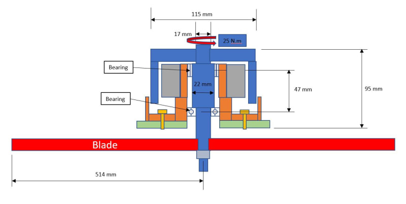
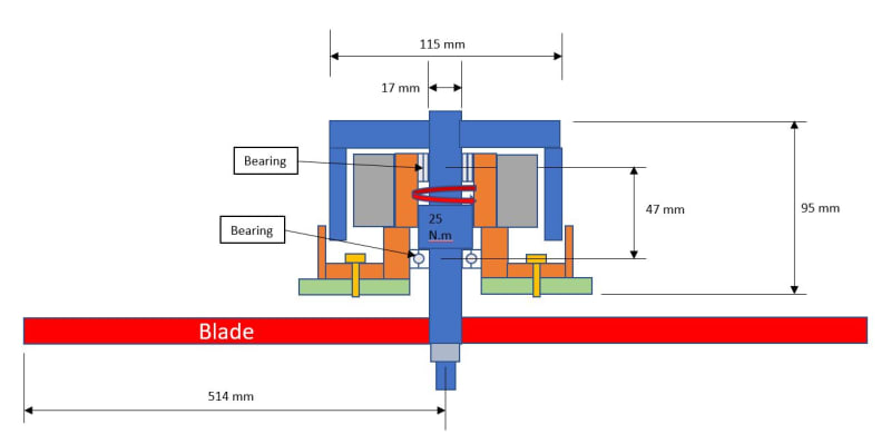
Can somebody guide me on how to calculate the max torque the shaft of the shaft in the image below?
It's an brushless outside rotor motor, the max torque the motor gives is 25 N.m
I would like to calculate the max torque in the shaft if the blade a 5,000 RPM hits a rock and stops.
torque_question_h8zdqe.jpg


Thanks in advance.
 
Replies continue below

Recommended for you

The resisting torque should be same or slightly greater than 25Nm to maintain shaft in equilibrium of stopping condition.
 
A conservative approach would be to assume that all the rotational kinetic energy of the rotor is used to "wind up" the shaft, calculate the amount of torque required to deliver that degree of "wind up" and then add 25 Nm (because the motor will still be providing torque) to that.

A.
 
Rocks are easy. I've trashed two mower engines running over lengths of heavy gage wire.
 
Given the usual assumptions, you can't accurately estimate the peak torque. zeusfaber's approach is an upper bound estimate (a good thing). A wise person might put a slip joint between the rotor and the shaft such as a pair of nylon discs under compression.

Cheers

Greg Locock


New here? Try reading these, they might help FAQ731-376
 
Thanks all for your responses. I'm trying to get some guidance on how to approach this calculation to increase my knowledge.

I'm new here. I think I'm not violating any rule. Do you think so Greg?
 
I seem to recall they used to put a shear key between the blade mount and crankshaft. Before they decided crankshafts were *cheaper* than shear keys :)

The problem with sloppy work is that the supply FAR EXCEEDS the demand
 
I think the shear key is a bit of internet myth. For a key to operate close enough to its shear strength to be protective of the shaft one would introduce far too many unnecessary failures. Also consider that the key doesn't shear cleanly and still damages the shaft as it fails.
 
A shear key does not have to fail completely. A "soft" key that allows 10 degrees of rotation before a complete stop of the crank compared to 1 degree, will reduce the impact force on the crank and other parts by a factor of ten.

However, the key still needs to be replaced, and if you have to pay someone to fix the mower, the economics often leads to replacing the mower. After all, there may be other damage and wear.

 
Well, I dunno about internet myth, but I seem to remember my (very much pre Net) B&S mower engines having an aluminum square key.

Neither here nor there these days :)

The problem with sloppy work is that the supply FAR EXCEEDS the demand
 
The man question here is how would I know the max torque reached by the spin of the blade, the data I have is that the motor gives 25 N.m at stall, but I would like to know how much torque the moment of inertia adds to the shaft.
Great comments by the way.
 
To be clear there are keys on both the cutting blade hub and on the flywheel. The flywheel key was aluminum, and if it deformed, the spark timing went off.
 
jil1969 said:
I think I'm not violating any rule.

Greg's not having a go at you - that's just a piece of helpful advice that appears in the signature block at the end of all his posts.

A.
 
Initial momentum divided by 0 time for deceleration = "E" as an old school calculator would say. Or "division by zero error". Or "infinity", as you prefer.

The (more-or-less steady state) torque that the motor develops is irrelevant relative to what happens in the impact.

In reality, the time for deceleration won't be zero but will be extremely small. The blade will bend some, the shaft will twist some, the rock will move a bit, etc. But, predicting what this is going to be, is not possible with the information supplied.

One would hope that the means by which the blade is attached, has intentional design features to accommodate this. The blade certainly has some flexibility to it. Maybe there is a shear-pin that's designed to snap. Maybe the blade is secured to a drive flange with a couple of bolts that are intentional weak spots, designed to break off in this situation. Maybe the drive flange isn't one-piece with the motor shaft and there's something that amounts to a friction-clutch or overload-clutch in there.

Impact situations are not easy to analyse, and the outcome may involve something changing shape. Your (presumably modern) car is designed to protect its occupants if it is driven at 50 km/h straight into a solid immovable concrete wall. But it's designed to change shape in doing so, thus absorbing the energy of the impact.
 
I was just making sure, Zeus. thanks for clarifying.
 
The basic equation is torque = inertia * angular acceleration and angular acceleration is change in velocity / time. So hypothetically, if the blade stops instantaneously, then the torque is essentially infinite. So, beyond that, you have to make some assumption about the stopping time to get anything useful, but in any case, your motor's torque is essentially irrelevant, since you've stipulated that the blade stops, which means that any practical torque from the motor is overcome by the fact that the blade stops.

TTFN (ta ta for now)
I can do absolutely anything. I'm an expert! faq731-376 forum1529 Entire Forum list
 
zeusfarber said:
A conservative approach would be to assume that all the rotational kinetic energy of the rotor is used to "wind up" the shaft,

My emphasis.

"The rotor" is part of the motor. Not the entire rotating mass.
 
A 17 mm/.670" Ø shaft? with the blade hung out in space about 1.7 inches in space?
A 40 inch blade spinning 5000 rpm? 300 feet per minute tip speed?
How is the external rotor retained on the .67" shaft?
How is the blade affixed to the shaft?
What is the shaft made of?
A gasoline 17 HP engine ( much lower rpm and proportionally higher torque ) would have a 1.0 inch or larger output shaft.


I see sheared keys, bent shafts, pierced, torn mower decks, rotors set adrift, maybe even broken shafts in your future.

I'd try to pick my battle.
 
Tmoose,

It's actually an stepped shaft
17mm-22mm-17mm
The rotor is press-fitted to the shaft.
The blade is yoked to the shaft and a nut is installed.
Carbon Steel shaft.

shaft_eng_dcayjw.jpg
 
"yoked to the shaft"??

What does that mean?

Anyway that looks like your weak point and if this blade does stop dead then it will almost certainly snap there. The consequences for a 1m diam blade spinning at 5000 rpm could be very bad indeed.

This is not a calculatable thing as there are too many unknowns and possible options for what breaks first. IMHO.

Remember - More details = better answers
Also: If you get a response it's polite to respond to it.
 
Status
Not open for further replies.

Part and Inventory Search

Sponsor