jil1969
Mechanical
- Feb 18, 2014
- 6
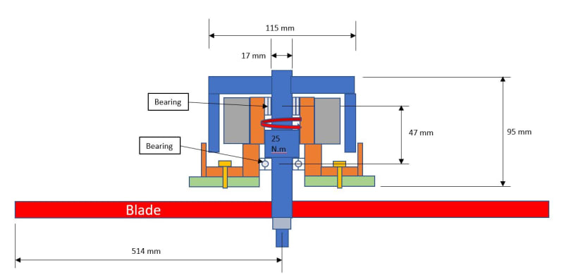
Can somebody guide me on how to calculate the max torque the shaft of the shaft in the image below?
It's an brushless outside rotor motor, the max torque the motor gives is 25 N.m
I would like to calculate the max torque in the shaft if the blade a 5,000 RPM hits a rock and stops.
Thanks in advance.
It's an brushless outside rotor motor, the max torque the motor gives is 25 N.m
I would like to calculate the max torque in the shaft if the blade a 5,000 RPM hits a rock and stops.
Thanks in advance.