Eng-Tips is the largest engineering community on the Internet

Intelligent Work Forums for Engineering Professionals

How to calculate Young's Modulus/Stiffness of Gyroid Lattice Structure in Abaqus CAE

Status
Not open for further replies.

Kunal Gide

Student
Oct 18, 2023
19
0
0
US
Hello,

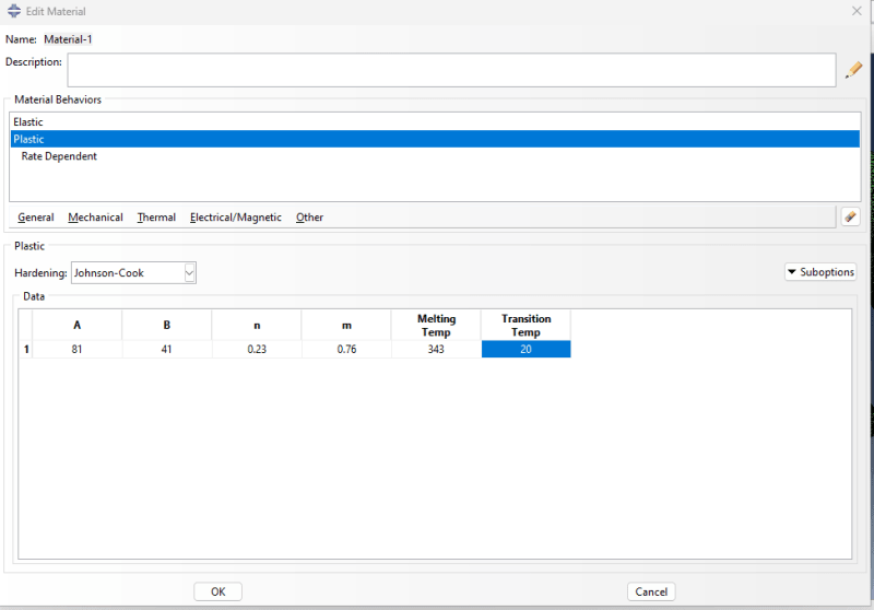
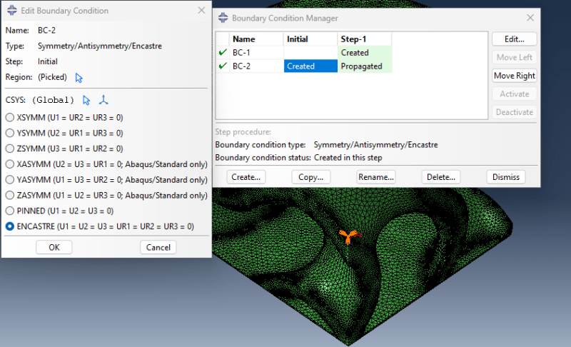
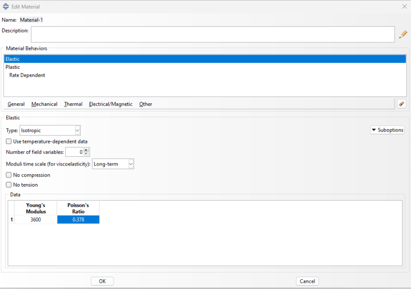
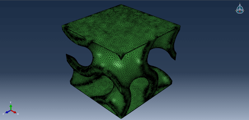
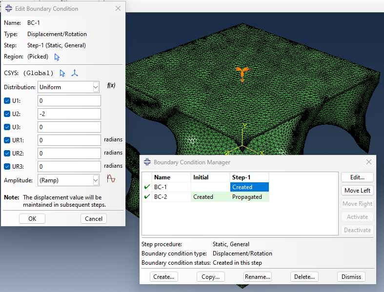
I am simulating a compression test on a gyroid lattice structure in abaqus cae. The geometry has solid surfaces on top and bottom and in between there is a gyroid lattice structure. The model is 10 mm in LXBXH.I applied a displacement of 2 mm on the top surface and fixed the bottom plate with encastre to replicate similar conditions to experimental compression testing. I have given material property only in the elastic region with E= 3.5 GPa and v= 0.378. The mesh size is 0.12 mm. The simulation runs and completes. Can anyone help me in how I can find the values of Young's Modulus or Stiffness of this structure?
Thank you.
 
Replies continue below

Recommended for you

Yes, I calculated using that method. My values are around 3.5 GPa but according to the literature the values for such lattice structure should be within the range of 350-600 MPa.

Thanks
 
I think the effective stiffness will very much depend on the scale of the lattice features. I.e. the ratio of the gyroid element thickness or thickness^2 to the overall structure cross section area.

"how can I calculate the stiffness of this structure?" Isn't that what you are asking when your ask about Young's modulus?
 
"how can I calculate the stiffness of this structure?" Isn't that what you are asking when you ask about Young's modulus YES. But I have also read youngs modulus is the material property and Stiffness considers the geometry effect. That is why I asked the question. I am confused about this.

How can I get my resulting modulus with the range of 350-600 MPa like in the literature?
 
I would do a series of tests where you either make the unit cell (10x10x10mm) larger (20mm? 30mm?) for the same thickness of gyroid infill (since you likely are using a 3d printer to create the infill, and thus are limited in the thickness of the infill to the smallest dimension the printer can reliably create), or make the 2mm displacement smaller...or perhaps better track the apparent gyroid stiffness versus those two variables. Yes, stiffness depends on the geometry as well as material, so you need to play with your test cube to try and separate the two effects.

edit: also, you might look into using a tensile load instead of a compression load, and compare results both ways.
 
Make sure that you are using correct stress/strain components, all inputs are in the correct units (your results with an order of magnitude discrepancy may suggest an issue with units) and you are gathering the data properly.

Also, look for some research papers where effective/equivalent elastic properties of lattice structures are determined using FEA.
 
I am using the LE22 and S22 components of stress and strain. I am selecting the entire model and taking the average of the values at each increment. I have double-checked the input values units.

Geometry is in mm, E is in MPa v is unitless. displacement in mm.
 
please post a picture of your model (embedded not linked).
also details of how you calculated the 3.5 GPa value
and post a copy of the paper with the 350-600 MPa value.
 
Agree with FEA - if your calculated value is 3.5 GPa (3500 MPa) and the range you are looking for is 350-600 MPa - it's likely you have an extra x/10 in your calculations somewhere
 
For getting the 3.5 GPa

In XY data- ODB field output-
position = centroid
Identifiers = Logarithmic Strain Components (LE) - LE22
Stress components (S)- S22

In the elements and nodes tab
method- Element Set- all elements

I click on save as and average values. then in operate on XY data I plot LE22 vs S22 absolute values and take the slope of the linear region.

Thanks
 
wait, you are taking the stress from the lattice elements? if so, this is not correct. you need to calculate a "stiffness" as an overall property, so take that applied total load divided by the total cross area encompassing the specimen to get an effective applied stress. then calculate a strain as the total end to end displacement divided by the specimen length. then divide the stress by strain.
 
Here are the images
MP2_ajhaqp.png
BC2_swqphs.png
MP1_l6os9l.png
Geometry_Lattice_zw7gta.png
BC1_l5xejv.png
 
@SWcomposites thank you for your suggestion. I have a few questions regarding it. What will be the cross section area with respect to my geometry. I am applying a fixed displacement so that I get convergence as when I applied pressure to the top surface it was not converging.

In which plane would the cross section for area calculation be. ALso would it work if I calculate the Reaction Force 2 at the last increment on RP1 and divide by the area of the top surface to calculate stress and Displacement at RP1 and divide by the total height of the lattice to get strain. and then divide the 2 to get the answer?
 
It seems that you are trying to find an effective/equivalent Young’s modulus. It will be different than the material’s modulus. For example, auxetic lattices can be made of steel (and thus have a Poisson’s ratio around 0.3) but due to their shape, the effective PR is negative. You can find the formulas for effective mechanical properties of lattice structures in literature but basically, you should measure the average displacements/strains in proper directions and relate them to the size of the structure and applied force (obtained as a reaction or contact force in this case).
 
ok, and I'm making an assumption about the "stiffness" value from literature that you are trying to correlate to (and it would be helpful to see that),

assuming you are putting a uniform Y-direction displacement on the top square surface (and assuming your model is essentially a "unit cell" that repeats) then you use the area of the square. Yes, use the total reaction force at the opposite end, divide by the area of the square to get an "effective stress". Divide the applied displacement value by the lattice height to get an applied strain. Then "effective stiffness" is stress/strain. Don't think you need a factor of 2. How does this value compare to the literature values?
 
Status
Not open for further replies.
Back
Top