Eng-Tips is the largest engineering community on the Internet

Intelligent Work Forums for Engineering Professionals

How to Change Convective Heat Transfer Coefficient of Coolant

Status
Not open for further replies.

SunRise2

Electrical
Mar 29, 2023
3
0
0
US
Capture_tmjqpm.png


I appreciate it if I can get answers to the following questions which are related to the attached cooling system diagram.

Q1.

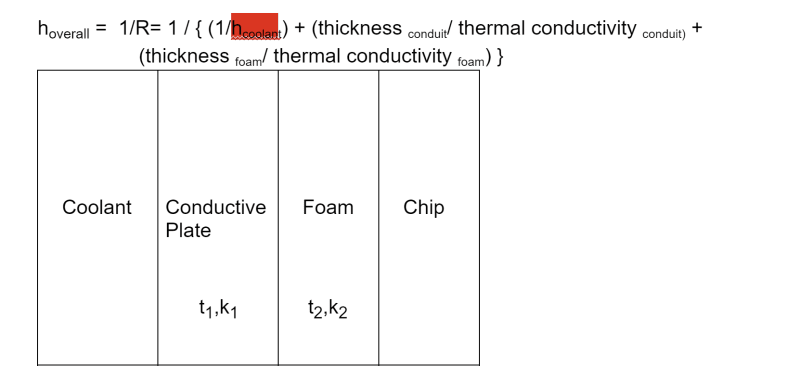
here t1 represents thickness of the pipe through which the coolant flows
t2 represents thickness of the foam which is sandwiched between the metal conduit and the silicon chip
k1 and k2 represent thermal conductivities of the metal conduit and the foam respectively
h(overall) represents the net heat transfer coefficient
h(coolant) represents

My understanding t1,t2,k1 and k2 are constant and only h(coolant) is variable. Thus the only way to change the net h is to change h(coolant). Please confirm.

This coolant is circulated by a pump.


Q2.

The chip temp shall not exceed 60 deg C and the coolant temp cannot be lowered below 30 deg C. The max chip input power is 300 watts.
The chip's surface area is 7.54cm x 5.85cm. Plugging these values into the following formula gives the minimum required heat transfer coefficient:

dE/dt= Q-W where Q=energy transfer due to heat, W=energy transfer due to power, assuming it is a steady state system, we get
Q=W
Q=h(overall) x A(chip surface area)x (temp of chip (i.e. 60) - temp of coolant(i.e. 30))
W=Power input to the chip

Q is -ve since the system i.e. chip is giving out heat ; Q= hxAx(temp of chip -temp of coolant)
W is also -ve since the system draws power i.e. work done on the system


-h x A x (60-30)= -300 watts
A= 7.54 x 5.85 cm^2= 44.109 cm^2=
h= 300/{ ( 44.109 x 30)=0.2267 W/cm^2 deg C = 8.26 Watts per meter-Kelvin

so the overall heat transfer coefficient has to be 8.26 to prevent the chip from overheating above 60 deg C when it draws 300 watts and the coolant is 30 deg C.

Now the only way to meet h (overall) 8.26 is to change the coolant's convective heat transfer coefficient. so wondering what factors the coolant's convective heat transfer coefficient depends upon ? may be coolant velocity and what other factors?
 
Replies continue below

Recommended for you

My understanding t1,t2,k1 and k2 are constant and only h(coolant) is variable. Thus the only way to change the net h is to change h(coolant). Please confirm.

Q1>> You can change both thickness and material for foam and possibly the plate, so that's part of what you are trying to design for. Likewise, you can change the type of coolant and its flow rate.
Q2>> As with the previous answer, you can change the type of coolant and its flow rate, as well as possibly the interaction surface area, say, with conventional fins or pin fins.

TTFN (ta ta for now)
I can do absolutely anything. I'm an expert! faq731-376 forum1529 Entire Forum list
 
You need to add the ID coolant boundary lay resistance, and all of the interface resistances.
The interfaces are likely more resistance than the layers of materials.
In reality the boundary layer may be the largest resistance in the entire system.
Change the tube to an erosion resistant alloy (high strength and thin wall SS) and then run the flow velocity as high as you can handle.
I have seen HX using 2205 or AL-6XN tubes running water at >50ft/sec.
The are loud and it take a lot of pump power but it buys a lot of heat transfer.

= = = = = = = = = = = = = = = = = = = =
P.E. Metallurgy, consulting work welcomed
 
If your feed coolant cannot be lower than 35degC, then why have you used 30degC as feed coolant temp? Also, better to use LMTD. Exit temp for coolant will depend on flowrate.
Generally speaking, foam has a relatively much lower thermal conductivity than the pipe conduit metal wall, so it may turn out to be the biggest resistance to heat transfer ( foam layer resistance even lower than 1/h_coolant). See if you can find a high thermal conductivity foam; and obviously the thinner it is, the better.
 
Possibly one other thing needs investigation - is the limit of 60 C for the chip SURFACE (and if so, which one? the one nearest the foam?), or is it for certain components embedded within the chip material (such as a specific junction)?

Converting energy to motion for more than half a century
 
Have thought of an alternative method to keep the chip cool such as by the chip by mounting an external fan just as it is being done with PC's.
 
Status
Not open for further replies.
Back
Top