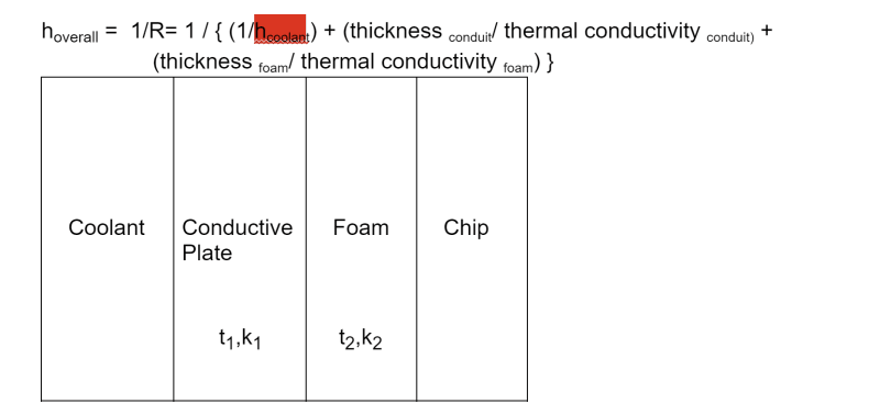
I appreciate it if I can get answers to the following questions which are related to the attached cooling system diagram.
Q1.
here t1 represents thickness of the pipe through which the coolant flows
t2 represents thickness of the foam which is sandwiched between the metal conduit and the silicon chip
k1 and k2 represent thermal conductivities of the metal conduit and the foam respectively
h(overall) represents the net heat transfer coefficient
h(coolant) represents
My understanding t1,t2,k1 and k2 are constant and only h(coolant) is variable. Thus the only way to change the net h is to change h(coolant). Please confirm.
This coolant is circulated by a pump.
Q2.
The chip temp shall not exceed 60 deg C and the coolant temp cannot be lowered below 30 deg C. The max chip input power is 300 watts.
The chip's surface area is 7.54cm x 5.85cm. Plugging these values into the following formula gives the minimum required heat transfer coefficient:
dE/dt= Q-W where Q=energy transfer due to heat, W=energy transfer due to power, assuming it is a steady state system, we get
Q=W
Q=h(overall) x A(chip surface area)x (temp of chip (i.e. 60) - temp of coolant(i.e. 30))
W=Power input to the chip
Q is -ve since the system i.e. chip is giving out heat ; Q= hxAx(temp of chip -temp of coolant)
W is also -ve since the system draws power i.e. work done on the system
-h x A x (60-30)= -300 watts
A= 7.54 x 5.85 cm^2= 44.109 cm^2=
h= 300/{ ( 44.109 x 30)=0.2267 W/cm^2 deg C = 8.26 Watts per meter-Kelvin
so the overall heat transfer coefficient has to be 8.26 to prevent the chip from overheating above 60 deg C when it draws 300 watts and the coolant is 30 deg C.
Now the only way to meet h (overall) 8.26 is to change the coolant's convective heat transfer coefficient. so wondering what factors the coolant's convective heat transfer coefficient depends upon ? may be coolant velocity and what other factors?
