Which software do you use ? Various FEA programs offer different techniques for shell and solid connections (which are tricky because of the difference in available nodal DOFs).
Hello!,
The title of the post was "how to connect shell to solids", but later you ask for seamwelds, and this is a different question.
For the title question the answer is easy: use GLUE EDGE-TO-FACE for a T-JOINT like of the edge of the shell with the face of the solid, o GLUE SURFACE-TO-SURFACE when both shell and solid element fades are parallel, surely your FEA code will allow this type of connection. We have RIGID elements RBE2 as well, but I prefer GLUE, is more efficient. Or you can insert a little the shell mesh in the solid mesh and merge nodes to account for rotation, but this is more complex.
In the FEA code I run an option to glue elements together during a solution is available with Simcenter Nastran. GLUE is a simple and effective method to join meshes which are dissimilar. It correctly transfers displacement and loads resulting in an accurate strain and stress condition at the interface. The grid points on glued edges and surfaces do not need to be coincident. Glue creates stiff springs or a weld like connection to prevent relative motion in all directions, see my blog:
But in your picture the connection regions seems to be a seamweld line, then this another history: GLUE is for regions where not a big stress gradient exist because the FEA code take the control for the end user, but if you need to perform a fatigue analysis in the seam weld then my preferred method is either mesh all with shell elements merging nodes (classical method), or mesh all with solid elements, but not mixing.
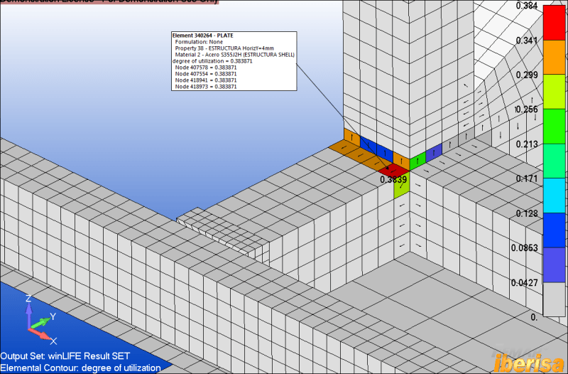
This a picture of mine from a project where fatigue analysis in the seamweld was requested from contractor, here I use winLIFE with FEMAP & Simcenter Nastran (by the way, GLUE edge-to-face shell-to-solid was used in regions far away from the area of interest):
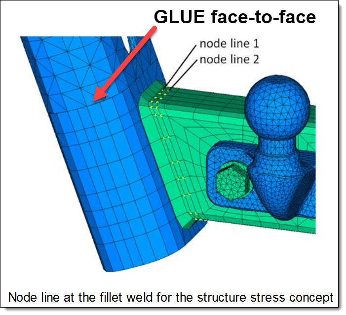
For fatigue analysis in seamwelds from solid models the method is modelling the actual geometry of the weld and use the structure stress concept with linear extrapolation, where we keep to the defined distances between the node-rows of the fillet weld, as shown by the nodes in the diagram marked in yellow.
The distance of node line 1 is 0.4 x the thickness of the steel of the weld seam and the distance of node line 2 is 1 x the thickness of the steel of the weld seam. With the steel thickness of the rectangle profile at 7.1mm, node line 1 is therefore 2.84mm and the node line 2 accordingly 7.1mm away from the fillet weld.
Well, you see, fatigue analysis is another history ...
Best regards,
Blas.
~~~~~~~~~~~~~~~~~~~~~~
Blas Molero Hidalgo
Ingeniero Industrial
Director
Abaqus documentation deals a bit with shell to solid connection. You can find ideas here: [URL unfurl="true"]https://abaqus-docs.mit.edu/2017/English/SIMACAECSTRefMap/simacst-c-shelltosolidcoup.htm[/url]
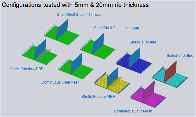
You can also find more ideas on google. Then you have to see whether you can apply it using your FEA solver. My recommendation would be to try different solutions on a simpler mesh to see which one works best, and which ones are the most practical to use in your context.