Continue to Site

Eng-Tips is the largest engineering community on the Internet

Intelligent Work Forums for Engineering Professionals

  • Congratulations IDS on being selected by the Eng-Tips community for having the most helpful posts in the forums last week. Way to Go!

How to connect two bones (with some space due to no cartilage) in Abaqus

Status
Not open for further replies.

Liangliang Xiang

Bioengineer
Apr 13, 2020
13
Hi all,
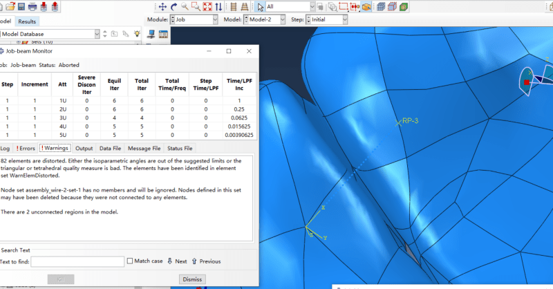
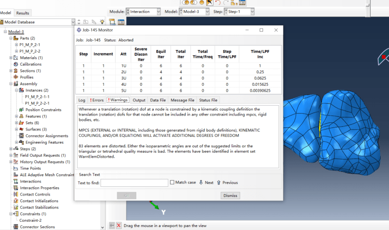
The result showed there are to 2 unconnected regions due to space exists between bones.
How to connect two bones (with some space due to no cartilage) in Abaqus?
Many thanks!
Abaqus_1m_2_x7etqi.png
Abaqus_1m_ymowhn.png
 
Replies continue below

Recommended for you

You can use connectors or spring elements to simulate ligaments that connect bones in joints.
 
Make sure that both ends of the connector (reference points) are attached to the bone. You can use kinematic coupling constraint for this purpose.
 
Thanks, let me try it first.
And if I can add cartilage between bones in Solidworks before inputting to Abaqus, if yes how to do it?
 
It would be best to model cartilage as separate parts positioned properly between bones. Then in Abaqus you can define contact between them or tie them if necessary.
 
“model cartilage as separate parts positioned properly between bones”
I'm wondering to know how to do this. Could you give me some advice?
 
I assume that you obtained this geometry from segmentation of CT or MR images. Either use them again to add cartilage or model cartilage from scratch in CAD software.

There are some scientific articles that might be helpful for you. For example:
- "Modeling and stress analyses of a normal foot-ankle and a prosthetic foot-ankle complex" by M. Ozen et al.
- "Finite Element Modeling of the Human Foot and Footwear" by J. Tak-Man Cheung et al.
 
Let's do a mind experiment: Imagine you shrink wrap any two bones across a joint and, then, imagine you create a solid geometry out of that shrink wrapped object. If you now remove the two bones from the shrink wrapped solid, you will be left with the cartilaginous part.

Now, to accomplish this, there are multiple options. As FEAway has noted, if you have a medical image stack for this set of bones, then you can simply create a mask for the region in one of the tools out there (Mimics, Simpleware, Amira, Slicer3D, Segment, ..). Then, you can mesh the masked region and write it out as a separate part entity.

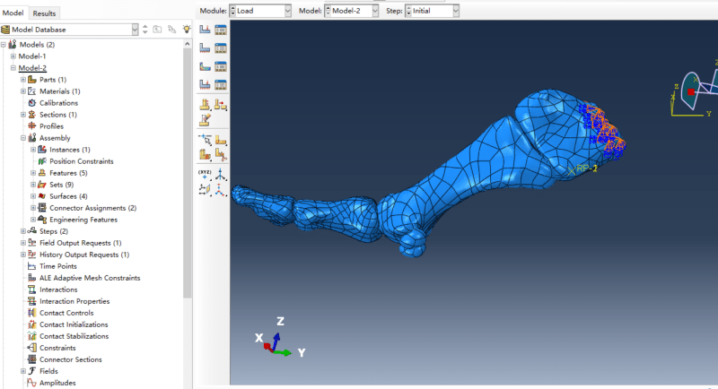
Noticing CAD geometry for these bones in the images you have uploaded, I am guessing the geometry was built in a CAD tool so the previous option may not work. Now, to the next mind experiment with the CAD geometry: Imagine creating a 3D smooth spline that is orthogonal to the cartilage and the bones near the joint (you don't have to be extremely accurate here), and then, imagine you create planes orthogonal to the spline at precisely known anatomical locations. Looking into each one of those planes, you can create a smooth spline around the region of interest (in this case, the missing cartilage). Once you are done doing this for every plane, you can use the loft feature to create a solid geometric entity for the cartilage. It is not going to be as straightforward but if you think this through and come up with minor adjustments, this option will work out well.

There are pre-processors like HyperMesh, ANSA, etc. that let you do the shrink wrapping.

*********************************************************
Are you new to this forum? If so, please read these FAQs:

 
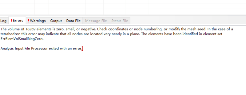
Check this set named ErrElemVolSmallNegZero. Such error is often caused by too high tolerance of tie constraint - it connects nodes that are located far from each other. As a result, elements may become stretched too much.
 
Status
Not open for further replies.

Part and Inventory Search

Sponsor