Continue to Site

Eng-Tips is the largest engineering community on the Internet

Intelligent Work Forums for Engineering Professionals

  • Congratulations waross on being selected by the Eng-Tips community for having the most helpful posts in the forums last week. Way to Go!

How to create involute gear

Status
Not open for further replies.

niedzviedz

Mechanical
Apr 1, 2012
307
Hello everyone.

I have faced problem with create involute gear in NX. First of all in Cartesian coordinates the involute of a circle has the parametric equation:
Code:
x=r*(cosΘ+ΘsinΘ)
y=r*(sinΘ-ΘcosΘ)
In NX there is law curve -> law by equation but when I put this two equation I get line. What I do wrong?

I also found this manual:

Link

but when I create gear with small numbers of teeth the shape of teeth doesn't match shape of co-working gear. In attachment I put my gear with imported geometry from Hasco to show problem. Anyone have forced similar problem and can help me?

With best regards
Michael
 
 http://files.engineering.com/getfile.aspx?folder=340ee5d1-6fad-48c1-a877-0028f8390174&file=gear.7z
Replies continue below

Recommended for you

I have this values:

Code:
t=0
xt=r*sin(t*360)-2*pi()*r*(t*360)/360*cos(t*360)
yt=r*cos(t*360)+2*pi()*r*(t*360)/360*sin(t*360)
I also tried
Code:
xt=r*sin(t)-r*t*cos(t)
yt=r*cos(t)+r*t*sin(t)
but I get line. Please look at the attached pictures.
Link
Link
The main problem is, when I create gear with small no of tooth for example z=20, there are some differences between my model and imported geometry from hasco. There are also collisions with co-working gear. Do You remember which function You used to create law curve?


With best regards
Michael
 
Attached is a zip containing several different GRIP and User Function programs that will create gears. Perhaps you might be able to use one of them for your task. After downloading the file, edit the file extension from .zipper to .zip before attempting to extract the files.

John R. Baker, P.E.
Product 'Evangelist'
Product Engineering Software
Siemens PLM Software Inc.
Digital Factory
Cypress, CA
Siemens PLM:
UG/NX Museum:

To an Engineer, the glass is twice as big as it needs to be.
 
 http://files.engineering.com/getfile.aspx?folder=8e61e975-92ca-4dd8-8ad8-31637f1de0dd&file=Gears.zipper
Yes Cowski You have right but:
On 14-1/2°PA gears undercutting occurs where a number of teeth is less than 32 and for 20° PA less than 18. Since this condition becomes more severe as tooth numbers decrease, it is recommended that the minimum number of teeth be 16 for 14-1/2° PA and 13 for 20° PA.
I had taught that
Code:
Z[sub]limit[/sub]=2*y/sin[sup]2[/sup]alpha.
so for normal tooth y=1 
and for alpha=20° 
Z[sub]lim[/sub]=17
So to prevent undercut I choose Z=20 to small gear. I think the main problem if in involute function or in angle.


With best regards
Michael
 
Thanks John I will try your solution. Do you have any manuals about law curve by equation, because in documentation there is only one example.


With best regards
Michael
 
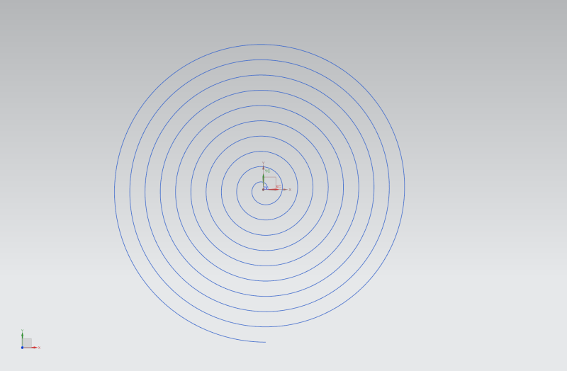
10_turns_involute_ll9r0p.png

And here - correct involute curve, 10 turns.
Be happy!
 
Thanks everyone for help. Tomorrow I will try Yours examples.

With best regards
Michael
 
Look in your NX installation, in the folder \Program Files\Siemens\NX 10.0\UGOPEN\SNAP\Examples\More Examples\Gear. There you will find a VB program that creates involute gears. It uses SNAP functions, but, if you don't have SNAP, it should be easy to adapt to use NX/Opejn functions, instead.

Part of that program is a function that calculates a point on an involute curve, as follows:

Code:
   ' Calculates positions on a segment of an involute curve   
   Private Shared Function InvoluteFunction(data As Object, u As Double) As Position

      ' Note that the involute curve here is parameterised by radial distance from the origin (r).
      ' The more common approach is to parameterise by angle (theta) but this causes a
      ' singularity at the start point (derivative vector has zero length), which leads 
      ' to a nasty Bezier curve whose first and second poles coincide.

      Dim params  As Double() = CType(data, Double())

      Dim a   = params(0)         ' Radius of base circle of involute
      Dim r0  = params(1)         ' Radial parameter value at start point of involute segment
      Dim r1  = params(2)         ' Radial parameter value at end   point of involute segment
      Dim r = r0 + u * (r1 - r0)

      Dim theta As Double = System.Math.Sqrt(r*r - a*a)/a
      Dim x As Double = a * ( System.Math.Cos(theta) + theta * System.Math.Sin(theta) )
      Dim y As Double = a * ( System.Math.Sin(theta) - theta * System.Math.Cos(theta) )

      return new Position(x, y, 0)

   End Function
Note the comment about the singularity at the start of the curve. It's possible that this is causing a problem in the Law Curve function.

In some cases, the involute curve is extended with a straight line. This might be related to the "undercut" idea mentioned in cowski's answer
 
Status
Not open for further replies.

Part and Inventory Search

Sponsor