Eng-Tips is the largest engineering community on the Internet

Intelligent Work Forums for Engineering Professionals

  • Congratulations waross on being selected by the Eng-Tips community for having the most helpful posts in the forums last week. Way to Go!

How to Deal with an Inclined Rafter 1

Status
Not open for further replies.

Abuh001

Civil/Environmental
Jan 24, 2018
28
GB
Ok, lets say you have a rafter which is 3m long in plan and inclined at a 40 degree angle, how do you account for the incline. I normal adjust the loading, say 1KN/m by dividing by cos(40) so 1/(cos40) = 1.31 KN/m and then design it. However, would it be better to adjust the length instead of the loading. So dividing 3/cos(40) to give you 3.92m in length.

This makes a bit of difference when working with timber and trying to calculate deflection. Would be really grateful if I could hear your opinions. Thanks
 
Replies continue below

Recommended for you

The axial component does not contribute to deflection, so to calculate deflection:
w = 1*cos[sup]2[/sup](40) and L = 3/cos(40).

To calculate bending moment, it makes no difference whether you consider the horizontal span or the sloping span. Either way it is 1*3[sup]2[/sup]/8.


BA
 
Thanks for the response.

Could you explain how you cos^2(40)?
 
A sketch would help because I may be misinterpreting your geometry...

but if your rafter is 3m and sloping 40 deg, then the horizontal distance between supports would be cos40*3 = 2.3m. Use this for bending moment for vertical loads. For deflection, use the actual length of the member, 3m, and apply the component of your loads that is perpendicular to the rafter.


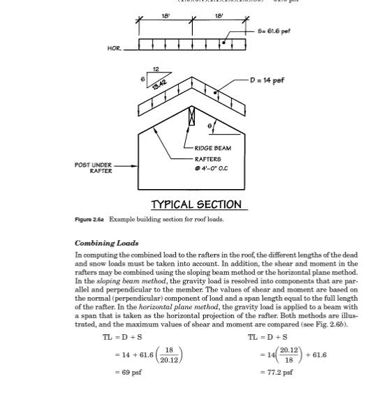
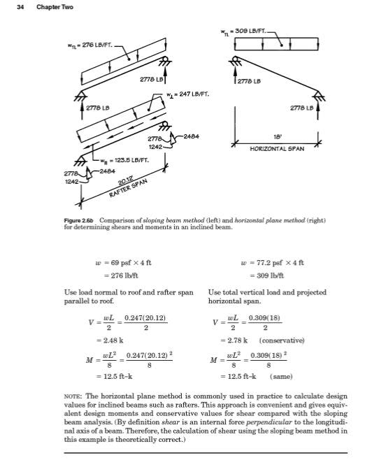
These pages are from Donald Breyer's Design of Wood Structures-ASD/LRFD 7th Edition. It describes the two methods used for sloped rafters.
Capture1_pg2u8g.jpg

Capture_mjscwn.jpg

Screenshots are from the book's free preview on Amazon.
 

Abuh001 said:
Could you explain how you cos^2(40)?

You stated that your load was 1 kn/m. I took that to mean a load per lineal meter of horizontal surface. So, when we consider a sloping surface, 1 kn of gravity load is spread over a greater length of sloping surface, namely 1/cos40. To state this a different way, the gravity load on the sloping surface is 1*cos40 per lineal meter. Resolving this load into axial and normal components gives 1.cos40.sin40 and 1.cos[sup]2[/sup]40 respectively.


BA
 
Don't forget to multiply the dead load deflections by 2 to account for long term creep. See appendix in NDS. If the roofing has a uniform pattern, like flat concrete tiles, any code maximum deflections will be clearly visible.
 
Status
Not open for further replies.

Part and Inventory Search

Sponsor

Back
Top