Continue to Site

Eng-Tips is the largest engineering community on the Internet

Intelligent Work Forums for Engineering Professionals

  • Congratulations waross on being selected by the Eng-Tips community for having the most helpful posts in the forums last week. Way to Go!

How to design a ledger board 1

Status
Not open for further replies.

Algohi

Structural
Apr 3, 2022
12
Is there any resource where it shows how to design a ledger board?

The problem is that I am having a commercial building that does not satisfy part 9 (NBC 2015) and should be designed according to part 4 but there is nowhere in the code that specifies the requirement of the ledger board except 9.20.17.5
 
Replies continue below

Recommended for you

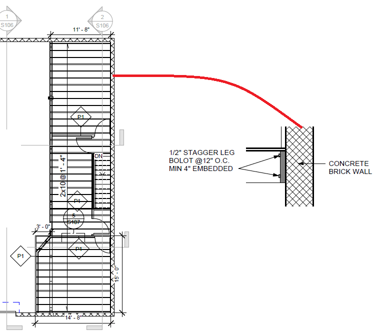
Can you provide some sketches of the situation and we could provide guidance at that point.

Generally speaking however, you design your ledger to span between points of attachment for whatever loads are imparted to it by the framing.
 
Screenshot_2022-04-11_085905_ek99yk.png
 
Generally how I'd be designing this ledger is for the ledger material itself to span between bottom bolts, therefore 24" span, and have the top bolts for eccentricity rectification only.

12" is a really weird spacing for bolts when your joists are at 16" o/c. Generally I try to make the spacing of the bolts the same, or a multiple of the joist spacing, to attempt to avoid conflicts between bolts and joists.
 
@jayrod12
It is clear for designing the bolts (to resist shear) but what about the bord itself?
Do I design the bord for bending and shear between anchorages as a continuous or simply supported?
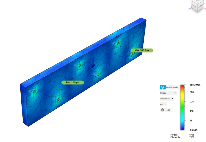
Should I do FEM analysis for this case as the stress will be complicated due to the geometry?
 
It's not that complicated. I'd be designing it as if simple span. I believe you are overly complicating the design of this. It's essentially fully braced by the flush framed joists.

You'll also want to take a look at the design of the diaphragm for any wind loads in the left-right direction. It appears to be a really long narrow diaphragm. The connection of the plywood to the last joist to the wall will be more critical than this load-bearing ledger design.
 
I have never even checked the span of a wood ledger between bolts. Typically, the bolt design values are so low that it would not be an issue.
 
For the bolt shown above, I used the NBC table:

Again, this building does not satisfy part 9 of the code. That is where I am stuck.

Screenshot_2022-04-11_092258_l9mrki.png
 
So run the actual numbers. If the building doesn't qualify as a part 9 building, then you need to get your head out of part 9. And if you aren't sure how to design the bolts yourself, are you sure you're the one who should be designing the rest of the building?
 
The structure is an offices inside a building and the drawing shows the roof of the offices.
The building already exists.

The issue here is not "design the bolts"; which is simple. The issue here is what is the suitable size of the ledger board itself.

See how the state of stress is complicated to be modeled as a bending behavior of a simply supported span.

Screenshot_2022-04-11_184537_cqykjh.png
 
Algohi - are you using FEM to design a wood ledger board? Are you familiar with the expression "measure with a micrometer, mark with a crayon, and cut with an axe"?

You have bolts at 12" on center. The wood will not develop enough bending stresses over those short spans to matter. Shear, sure, but that's largely a function of the bolt pattern. If the bolts don't rip through the board, the board is going to fine. I think that's what XR was getting at.

If you're that worried though, a quick hand calc using multispan beam tables is easy enough. For a uniform load and a 7 span beam, worst case moment will be wl[sup]2[/sup]*(-.106) and the worst reaction will be wl*86/142. w = uniform load and l = bolt spacing.
 
phamENG-
Got it.
Great info and many thanks.
I will look at the expression also.
 
If using dimensioned lumber, I would put them in one row, about 1/3 up from the bottom. If you get shrinkage, the two rows of bolts may cause a horizontal split in the ledger. The depth should be a similar depth of the floor joist and the thickness should be about 2"or 3" or whatever you need to develop the fasteners. I don't think I've ever calculated a deflection or moment for a ledger; the depth to span becomes so significant that I don't think beam theory is applicable. I should have added, it's the first time I've seen FEM used for a ledger board in over 50 years. I really missed out a lot! [pipe]

Rather than think climate change and the corona virus as science, think of it as the wrath of God. Do you feel any better?

-Dik
 
Did you account for clamping force in the FEM? Wonder how that would change the stresses?
 
So I did all the suggested solutions above and one question came up:
"The ledger calculations does not address the governing factor which is the stress in the ledger perpendicular to grain at the bolt location"

Any idea about that?
I can use the FEM to find the stress perpendicular to the longitudinal direction (at y-direction in the above FEM) and compare that with the wood strength in the needed direction but is there another way to do that (practical engineering method)?


Thanks to all of you guys.
 
Can you even use FEM on wood? I thought the material had to be isotropic.
 
OP said:
is there another way to do that (practical engineering method)?

Stress = force / area. Divide the shear in the bolt by the bearing area of the bolt on the wood. There are tables in the NDS with these values. When the answer is different than what FEM shows, scrap the FEM.
 
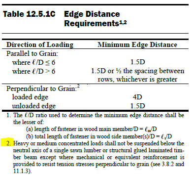
Tension perpendicular to grain is not detailed or included in NDS, other than to simply say "don't do it". With that said, I don't see stress perpendicular to grain being a terribly large issue with the bolt pattern you show in your FEM model above. Rather than approach this as FEM, simply draw a free body diagram at each bolt location to determine stresses locally and come to this conclusion yourself?

Table_nynrte.png
 
Status
Not open for further replies.

Part and Inventory Search

Sponsor