Eng-Tips is the largest engineering community on the Internet

Intelligent Work Forums for Engineering Professionals

How to design welding drawing

Status
Not open for further replies.

Lemur117

Industrial
Oct 18, 2018
3
0
0
RU
Hi all.
How can I design welding drawing according to ISO or ANSI standard?
I need to create general view of our device and show all welding joints on it. It's easy to done with ISO 2553, but I need create specification of welding joints.
Now I working with GOST. I try to search answer in Google, with different requests, but found nothing.
According to GOST it looks like here. There are welding arrows with numbers on drawing, witch indicates welding joints.
%D0%A1%D0%BD%D0%B8%D0%BC%D0%BE%D0%BA6_qefeqm.jpg


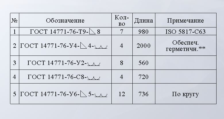
May be you can show me drawing with welding joints and specification?
Sorry for my English.
 
Replies continue below

Recommended for you

Lemur117:
Are you actually a college educated engineer? It sounds like you would do well to gain some basic knowledge in welding design, welding processes, etc. and some fundamentals in engineering, like Strength of Materials, manufacturing processes, etc. In America, our welding authority is the AWS (American Welding Society), and they have a wealth of info., stds. and specs. on welding, such as their “Welding Handbook” series of volumes. Then, take a look at Omer W. Blodgett’s books, “Design of Weldments” and “Design of Welded Structures,” from the Lincoln Arc Welding Foundation. They cover these topics in some detail. They are inexpensive and a really very good ref. books for engineers doing welding design for various structures and details. Also, from Lincoln Electric are “Metals and How to Weld Them,” and “The Procedure Handbook of Arc Welding,” which are very good texts on the fundamentals of welding and welding design. ISO and ANSI Stds. are just slightly different, formalized stds., pulling all this info. together for an international audience. I really don’t make any sense out of the tabulation that you show in your OP. You probably should not be using some unknown software, software that you don’t understand very well, when you don’t have a good grasp of the basics of that industry or an understanding of the engineering fundamentals of that aspect of design. Today, engineering is going in a very dangerous directions with all its codes, standards and software; in that, there are a lot of people and companies out there who think that just because they have the cookbooks (codes, stds., software, etc.), but without any real knowledge of the subject matter (cooking or engineering, both by education, knowledge and experience), that they are actually cooks (or engineers). The former can make some really crappy cakes, sometimes downright dangerous to the general public.
 
I'm sorry. I had used wrong word.
I dont ask, how to design anything. It's my job since 2010. And I'm doing it good.
I'm searching any standard, using witch, I can draw table and fill it by information about used welding joints.
 
A discussion over on the AWS site -

A key statement that I think is an answer to what you are asking about -
"In general, (weld maps ) can be an assy drawing with weld symbols that reference the WPS numbers."

"The information must provide details on weld number, wps number, pqr number, material type, thickness, and joint design. It is also wise to call out heat treat and nde requirements."

A rough looking example with provisions to become a real time inspection document.
 
Tmoose, great! Thanks, good link.

MJCronin, component is a machine. Vacuum gripper and it's parts. Yes, it's good drawing, but GOST. But good)

robyengIT, excellent! Take it to my lib.

Thank you all, I have answer for my question.
 
Status
Not open for further replies.
Back
Top