Continue to Site

Eng-Tips is the largest engineering community on the Internet

Intelligent Work Forums for Engineering Professionals

  • Congratulations KootK on being selected by the Eng-Tips community for having the most helpful posts in the forums last week. Way to Go!

How to determine moment stresses in plywood cross section. 1

Status
Not open for further replies.

bluestar9k

Structural
Nov 11, 2016
31
Problem: Remove a 2”x4” Beam and replace with plywood.

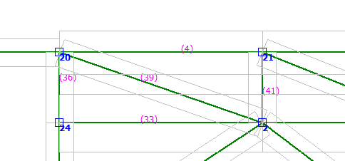
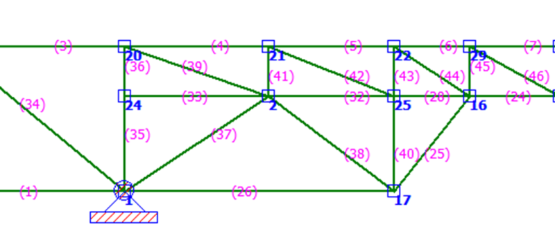
Shown below is a section of truss I have been working on.
The problem is the spacing between the top and bottom chords is too small for a diagonal member. So I have elected to replace the diagonal member with plywood. I have the axial, shear and moment forces acting on beam 39 (the beam to be replaced) and I have been able to convert the axial and shear force into X and Y axis force to determine the loading on the plywood. However, I am having difficulty determining how to distribute the moment forces in the X and Y axis or even evaluate the moment stresses on the cross section of the plywood and this is where I need guidance.
TrussSection_gfehol.png

Nodes
2, 24, 20, 21

Beams: Southern Pine Grade 2.
33: 2”x8”
36: 2”x4”
4: 2”x6”
41: 2”x4”

Beam 39: Southern Pine Grade 2.
Node 2:
-978 Lbs Tension; -11 Lbs Shear; -135 In-Lbs Moment
Node 20
978 Lbs Tension; 14 Lbs Shear; -198 In-Lbs Moment

Additional Considerations:
The open space between beam 4 and 33 is 2.5 inches. My intent is to rip a 2x4 down to 2.5 inches and glue that piece to both the top and bottom chords then glue and nail a continuous plywood gusset to both sides. I have also considered sandwiching a 20ga plate between the beams and the plywood if the stresses are too great for ½ or ¾ in plywood.
 
Replies continue below

Recommended for you

Beam 33 doesn't appear to be doing anything. What happens if you delete Node 24 and Beam 33?

BA
 
Additional Information.
Beam 39 is just 1 beam of 18 beams which needs to be replaced. This beam was the first beam to consider when working from left to right.

On the side issue, with respect to beam 33, here are the loadings.
Beam 33
Node 2
-308 Lbs Tension; -198 Lbs Shear; -3138 In-Lbs Moment
Node 24
308 Lbs Tension; -201 Lbs Shear; -2102 In-Lbs Moment

Again, the question is not about the structure; but, how to determine the moment stresses in a plywood cross-section so I can determine the plywood loading on the remaining 17 beams.
 
I'm confused. Are you loaded at the nodes only, or do you have loads applied in the middle of members?

I thought trusses were composed of 2-force members loaded at nodes. If you are pinned on both ends, then how are you carrying moment?
 
Joel,
I think he is analyzing the structure as a frame, not a pin jointed truss.

bluestar,
I understood your question well enough, but thought you were dealing with a design problem, not an existing structure. The answer is not clear but is likely dependent on how the moment gets into the plywood. Truss plates on the face of the plywood will engage only one or two plies.

BA
 
Hey Joel,
All loads are nodal loads and there are no middle-of-member loads.
All nodes are fixed joints in lieu of pinned joints; thus, transmitting moments.

Hey BA,
Yep, I am analyzing the truss structure as a frame.
Yep, it is a design problem.

Conceptually, the plywood plate will be glued and nailed continuously along the top and bottom chords thus transmitting all forces continuously between the chords and through the plywood plate. The strong axis of the plywood will be running horizontal. I would expect all plies of a plywood plate, parallel to the load, to carry load when the plate is mounted with glue and nails as in the case presented above. The load capacity of the plywood will be considered in two ways: via the parallel-ply section and via full-thickness section. I just need to convert moment into cross-sectional force and to determine which way to apple the force vector to complete my analysis.
 
Does the plywood plate extend from B4 to B33 and from B36 to B41? If so, I'm not sure that your frame analysis is appropriate because B4, B33 and B39 will be acting as a single member with axial force, shear and end moments. Conservatively, the force to be taken by the nails and glue on B4 and B33 would be the sum of end moments divided by the height. Nails and glue on B36 and B41 will carry the panel shear.


BA
 
Correct, the plywood will extend over all nodes.
Agreed, the section, with plywood attached, will act as a single integrated unit. Under this premise I had considered evaluating this section, and all adjacent sections, as an “All Plywood Beam” under the provisions of APA Supplement 5-12 with the exception of substituting sawed wood for the plywood flanges. An initial review of the document suggested a less conservative approach than the one initially under consideration. However, I may return to this option.

With respect to the moment stresses in the plywood, I had already considered your point of dividing a length into the moment to derive a force; however, I was unsure as to which length to take. I considered the full width between B36 and B41 because the plywood was continuously attached and would dissipate the moment into the chords. The other more conservative approach, as you had mentioned, was to use the height which is what I elected to do. However, when considering the height I was unsure as to which height to use, the height of open separation between the cords 2.5”; or the height between the nodes 9”; or the height between the closest course of nails between the chords 4.5”; or finally the distance from the node under consideration to any one of those points. Another factor affecting my considerations was do I divide that length by 2 because there was another moment at the opposite end also inducing force on the plywood.

All of the above considerations led me to post my original question. If the length could not be ascertained with any degree of confidence then I started to consider the moment stresses in the plywood. This was easy enough to do by taking the moment and dividing by the section modulus; however, I could not find any performance data on edge stress on plywood. Although, I am now beginning to wonder if I can apply the plywood “Shear-Through-Thickness” capacity in (Lbs/Ft) to the problem. If I divide the moment by section modulus I get PSI then if I multiply by the section thickness I get Lbs force and to get the final capacity I would multiply times the length and then again which length.

I have thrown several considerations out for comments and would appreciate thoughts or other approaches on the matter.
 
bluestar said:
However, when considering the height I was unsure as to which height to use, the height of open separation between the cords 2.5”; or the height between the nodes 9”; or the height between the closest course of nails between the chords 4.5”; or finally the distance from the node under consideration to any one of those points. Another factor affecting my considerations was do I divide that length by 2 because there was another moment at the opposite end also inducing force on the plywood.

My suggestion:
h = height between nodes (also c/c of nails and glue)
M = M1 + M2 if same sign but not less than Mmax if opposite sign (conservative)
F = M/h where F is the force connecting plywood to chord

BA
 
1) Are you sure that B33 is really the bottom chord? What are those two diagonal members below doing?

2) At the proportions you have here, you don't really have a truss. Rather, you have a composite beam. As such, I highly recommend that you design the plywood as a shear panel alone and forget the bending stresses. In all likelihood, adjacent plywood sheets will not be fastened together in a manner suitable for transferring moment anyhow. It sounds as though you've pretty much come to the same conclusion.

3) I have a hard time imaginining a scenario in which it would be appropriate to consider the ends of your web members fixed. I'd recommend revisiting that assumption.

4) Were it appropriate to design this as a truss, I would still recommend designing the plywood as a shear only panel as recommended by others above. The procedure:

4a) calc truss shear at 41 & 36. Distribute aling the vertical edges of the plywood panel.

4b) sum moments about the top left of the panel to determine the shear force delivered to the bottom edge of the panel.

4c) sum moments about the bottom left of the panel to determine the shear force delivered to the top edge of the panel.

For what it's worth, I spent some time in the 90's as a metal plate connected wood truss designer.

I like to debate structural engineering theory -- a lot. If I challenge you on something, know that I'm doing so because I respect your opinion enough to either change it or adopt it.
 
Why not just sheath both side of the chords and design it as a plywood beam? It's been a while - but I did that to a triangular poorly designed and built truss in my garage. Made sure that the chords had metal straps for continuity. Had a senior design class lecture where the professor used 8 foot high plywood wall to span a large span. For that, the detailing of the nailing was important. I don't think that using plywood for a member is a real good idea. You can only use the area of the lams orientated in the correct direction. The plywood properties use to be in the wood section of the UBC.

Be interesting on how you fabricate the connections.
 
Hey BA
Got it. Thanks for your input, it was quite clear and I greatly appreciate it.

Hey KootK
Thanks very much for helping out.
I was trying to keep the question as simple as possible; but, perhaps I should present the entire truss for clarity sake.
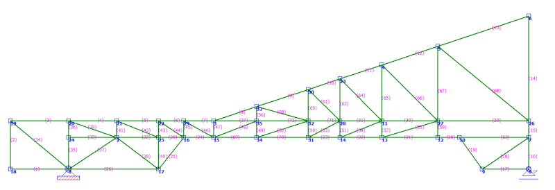
Configuration for Analysis

Truss_21A_-Truss_Analysis_dbcf4i.png


Internal Member Stresses

Truss_21A_-Beam_Stresses_z8walt.png


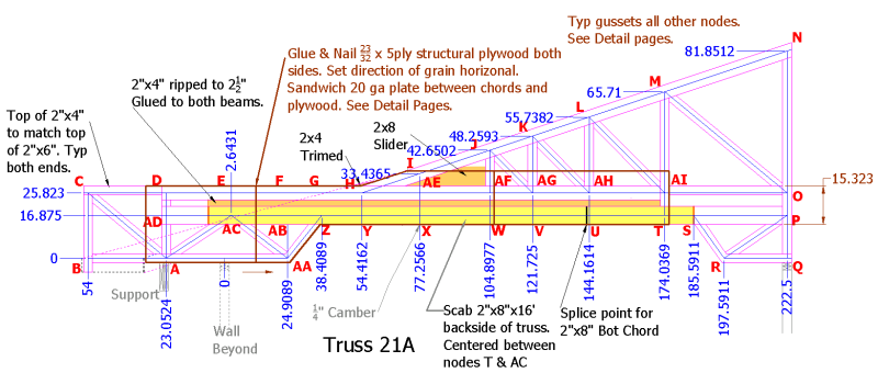
Configuration for Fabricate

Truss_21A_-Fabrication_k9oic7.png


1. Yep, as shown, B33 is part of the bottom chord and the diagonal members you referenced frame for a raised ceiling profile. Although, I have found those diagonal members do carry non-trivial loads.

2. Yep, I have tried many truss configurations and have found that only a composite beam has the capacity to handle the loads on and around Nodes 29, 16, 3, 15, 35 and 34.

Just as a side note; I had considered attaching a 10’ panel centered on the nodes mentioned above. At the butt joints between panels, the assumption was that there would be a discontinuity in the transfer of moments; however, all of the moment in one panel would end at the joint and the balance of stress would be transferred to the chords. Also, beyond the ends of the 10’ panel the calculated moments were not as critical. No splice plates were considered, in that the plywood panels were nailed to the TC & BC with only 2.5” separation and that will be filled. I have evaluated the shear, tension and compression, both parallel and perpendicular to the direction of veneer grain and loading falls within the adjusted capacity of the plywood. However, moment forces are still under consideration and it is the moment on B45 at nodes 29 that gives me grave concern, (5,963 in-Lb).

3. These trusses have to be fabricated on-site; because the site is quite remote and to access the site one must cross a low load-limit wood bridge and must navigate very narrow roads with very tight turning radius curves. Additionally, from what I have seen, on-site application of metal plates connectors were dangerously far from optimum which is why I elected to go with glued & nailed plywood gussets. The assumption that moments would be transmitted through the gusset plate was based on the consideration that if the loads on the gusset plate did not exceed the capacity of the gusset plate then the moment was transmitted. I would not make that assumption with common metal plate connectors. I also felt that by using moments in the analysis produced a more conservative design specifically with respect to buckling stresses in the beams. Is there a fault with this logic and if so please do advise?

4. Thank you for the procedure, it was clear and reasonable and greatly appreciated.

Your comment in item 2, “At the proportions you have, you don’t really have a truss.” has caused me to pause, AGAIN, because I too have previously considered treating the chords as a large contiguous beam. The assumption would be all external forces acting on the chords would be carried by the chords and plywood plates would only carry any shears, tensions and compressions stresses between the chords. I will be unable to find any performance data or a beam of such dimension; and, I can’t extrapolate because some properties diminish as the wood dimension increase and I am unsure if the rate of change is linear. Perhaps I can use the APA Supplement 5-12 as a guide for the analysis.

Koot, with your experience as a truss designer, I really do appreciate your insight.


Hey Oldrunner
Agree. FYI, as my design process progressed I removed the diagonal members because of the narrow space between the chords and replaced them with plywood sandwiched with a 20ga plate on one side. Then after performing numerical analysis I decided to combine the TC & BC into a box beam just as you have mentioned and as KootK had noted.
Also, you had mentioned interest in how the connections were to be fabricated, to answer that question I attached a draft of the fabrication drawing to illustrate those connections. Of course, any comment is certainly welcome.
 
OP said:
Koot, with your experience as a truss designer, I really do appreciate your insight.

You're welcome. You do show up with the wackiest truss profiles. It makes for interesting problem solving. That said, I would be remiss were I to fail to suggest the following two avenues of resolution:

1) Modify the truss layout within the roof plane envelope so that you have more conventional truss profiles.

2) Convince the building architectural designer to chose his roof and ceiling planes such that you have conventional truss profiles.

With the advent of software, we seem to have adopted that stance that any truss profile possible. And, while all truss profiles may well be possible, that does not necessarily mean that they are all advisable in my opinion. I don't love your truss. What you've got going on between G&H makes me shudder. Anyhow, on with answering the questions asked and making recommendations for improvement.

OP said:
Yep, as shown, B33 is part of the bottom chord and the diagonal members you referenced frame for a raised ceiling profile. Although, I have found those diagonal members do carry non-trivial loads.

The diagonal loads are probably carrying non-trivial loads because, to the left of Z, those members are becoming the bottom chord effectively. I'd either make them the bottom chord in earnest or adjust your configuration so that these members are just under build rather than integral parts of the truss proper.

OP said:
Yep, I have tried many truss configurations and have found that only a composite beam has the capacity to handle the loads on and around Nodes 29, 16, 3, 15, 35 and 34.

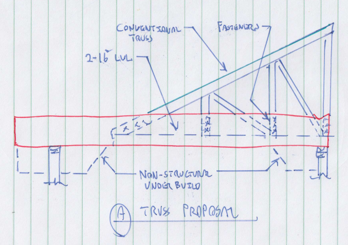
That's unsurprising. I think that a beam approach, composite or otherwise, will produce a simpler result. And I'd consider that all the more important here where the truss will be fabricated on site. I've proposed another potential solution in the sketch below. If the only structural element could be the LVL's, that might be even simpler.

OP said:
Additionally, from what I have seen, on-site application of metal plates connectors were dangerously far from optimum

Agreed.

OP said:
The assumption that moments would be transmitted through the gusset plate was based on the consideration that if the loads on the gusset plate did not exceed the capacity of the gusset plate then the moment was transmitted.

I feel that joints stiffness comes into play as well. Localized, nailed connections tend not to possess a great deal of rotational stiffness. Nail slip etc.

OP said:
I would not make that assumption with common metal plate connectors.

I'd take the reverse tack. I think that you'd get a more convincing moment connection with the tooth plates unless the extents of your plywood gusset will be very large.

OP said:
I also felt that by using moments in the analysis produced a more conservative design specifically with respect to buckling stresses in the beams. Is there a fault with this logic and if so please do advise?

I suspect that it would be more conservative for all purposes save deflection. Unnecessarily conservative really. Your design effort will be greatly reduced if you go with the standard assumption of pin ended web members. One way to justify the decision, one way or the other, is to run the truss both with and without joint fixity and quantify how much of the load winds up being resisted by the moments generated in the joints. If the load share resisted by true truss action is upwards of 90%, I'd say that you'd be fine to ignore the moments.

Capture_01_z4gxab.png


I like to debate structural engineering theory -- a lot. If I challenge you on something, know that I'm doing so because I respect your opinion enough to either change it or adopt it.
 
Hey KootK

KootK said:
You do show up with the wackiest truss profiles. It makes for interesting problem solving
Hahaha,… I’ll take that as an acknowledgement of my design creativity when faced with impossible constraints. 
Yep, I get responses similar to that a lot; most problems are easily solved with traditional approaches; however, what everybody else gets to see are the difficult problems.

KootK said:
Convince the building architectural designer to choose his roof and ceiling planes such that you have conventional truss profiles.
The roof profile is a traditional hip roof with gables over bay windows along with simple pan ceiling profile

KootK said:
…while all truss profiles may well be possible, that does not necessarily mean that they are all advisable in my opinion.
Perhaps true; however, when traditional truss profiles fall short more creative approaches should be examined and adopted when applicable.

KootK said:
What you've got going on between G&H makes me shudder
Yep, the bending at G & H was one of the top concerns; however, the stresses were well within the capacity of the beam specified. The real issue arose from the tension in the bottom chord and here I had to scab a 2x8 to meet the load requirement and this is evident when examining the beam stress plot.

KootK said:
The diagonal loads (members 25 & 26) are probably carrying non-trivial loads because, to the left of Z (node 16), those members are becoming the bottom chord effectively.
Actually, I’ll have to go with the numbers from the analysis program which indicates otherwise. (Yeah, yeah,… I know, not fair, you didn’t have access to the numbers.) Anyway, consider horizontal tensile loads from node 16 to the vertical support beams 35 & 36.
Truss_21A_Bottom_Chord_Queston_tg6vur.png


Bottom Chord
#28 2310 Lbs Tension
#32 651 Lbs Tension
#33 307 Lbs Tension
#39 978 Lbs Tension at 22 degrees (906 Lbs Horz)
#42 1079 Lbs Tension at 22 degrees (1000 Lbs Horz)
#44 896 Lbs Tension at 35 degrees (734 Lbs Horz)
#41 & #43 are in compression
Total tensile load in or transferred from Bottom Chord = 5,908 Lbs


Diagonal Member
#25 1614 Lbs Tension at 53 degrees (962 Lbs Horz)
#26 809 Lbs Tension
#38 312 Lbs Tension at 45 degrees (220 Lbs horz)
#37 & #40 are in compression.
Total tensile load transferred from Bottom Chord = 1,991 Lbs

The tensile load in the bottom chord is just shy of 3 times the load transferred by the diagonal members. So, I would say the bottom chord clearly functions as a bottom chord from one support to the other support.

KootK said:
Localized, nailed connections tend not to possess a great deal of rotational stiffness. Nail slip etc.
KootK said:
I think that you'd get a more convincing moment connection with the tooth plates unless the extents of your plywood gusset will be very large.
Actually, I would think the rotational stiffness of any connection has a direct correlation to the moment-arm of the connector. From what I have observed manufactured trusses have very small metal plate connectors thus yielding very small moment-arms. Where plywood gussets tend to be much larger and consequently have a much greater moment-arm. By having a greater moment-arm the stresses on the nails most distant from the node is much less than the stresses seen on the connector plates at their extremities. With higher moment stresses on the metal plates I would expect to observe tooth slippage along with thin plate buckling. Actually, I really would like to see a comparative study between plywood gussets and metal plate connectors; if anybody is aware of one could you please share the link. I would think this type of study has been done at one time or other.

KootK said:
Your design effort will be greatly reduced if you go with the standard assumption of pin ended web members.

I actually wrote my own truss analysis program; and, I limited the scope to only pin connections. My program compared favorably to the professional analysis program; however, when I started to consider moments in the frame I was surprised to see that members that passed in my program failed in the professional program. Why,… because of the buckling stresses that developed in the beams which I had not accounted for. This caused me concern and when considering the type of gussets I planned to use (glued and nailed) which would transmit moments I elected to use moments in the design. Actually, the design effort to include moments in the truss design is trivial. The real concern is the increased material necessary to handle some of the buckling stresses. In other words increased cost.


Thanks for the sketch. I really appreciate your effort. However, “I don’t love your truss”, hahaha Just kidding Koot.

Although, in all sincerity I am uncomfortable about the side-saddle truss and the eccentric loads it induces and I have never been fond of drilling into beams. With that set aside I can see incorporating some of your ideas.

If you will note in my design, that when I the remove of the diagonal members between the chords and then place the ripped 2x4 between the chords I effectively create a 2x16 LVL; ie, (2x8 + 2x6 + 2x2.5 all glued and nailed together) All I have to do is extend the 2x2.5 member to the support ends. The reason this was not extended originally is because the loading on the ends didn’t warrant it. One area of slight concern is building up the support on the left side. Several trusses sit on top of a double 2x12 which spans 10’ or so and there could be some lateral stability issues that need to be examined.

I do like the concept of removing the loads off the ceiling framing; although, as shown it would suggest toe nailing which may not be adequate for ceiling loads. So gusset plate and a diagonal member may be appropriate.

I would really feel much more comfortable if the conventional truss were set on top of the beam and attached with gusset plates. This would make the design much simpler by determining the point loading from the conventional truss and then apply those point loads to the design loads of the beam.

Finally, with the modifications mentioned, I really don’t see any significant change in the fundamental design so
I will probably still have to scab a 2x8 on the bottom of the beam to handle the tensile load. This will be determined by the truss analysis program.

Your rebuttal.  [thumbsup2]
 
Status
Not open for further replies.

Part and Inventory Search

Sponsor