Continue to Site

Eng-Tips is the largest engineering community on the Internet

Intelligent Work Forums for Engineering Professionals

  • Congratulations KootK on being selected by the Eng-Tips community for having the most helpful posts in the forums last week. Way to Go!

How to determine operating pressure of pressure vessel

Status
Not open for further replies.

zamakaze

Chemical
Sep 3, 2020
45
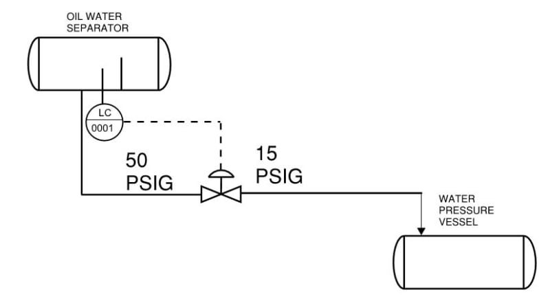
I have a oil water separator operating at 50 psig with a level control for interface. Water flows out of the level control valve to a pressure vessel. The level control valve is sized for p inlet = 50 psig and p outlet = 15 psig. The water pressure vessel has no blanketing or any positive pressure.
What will be the pressure inside the water pressure vessel. Will it be due to vapor pressure of water? Or will it be 15 psig? How to determine operating pressure of the water pressure vessel?
Capture_bqbptd.jpg
 
Replies continue below

Recommended for you

It should apparently be 15 psi, but that is not guaranteed. The pressure downstream of the valve will be 15 psig only if the pressure in the water tank is not greater than 15 psig. For example if a fire heated the vessel, its pressure could rise to well over 15 psig and I do not see a relief valve anywhere.

Einstein gave the same test to students every year. When asked why he would do something like that, "Because the answers had changed."
 
Thanks 1503-44,

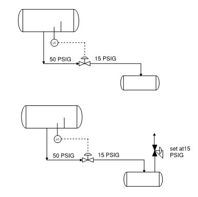
In case, The LCV is sized for Pinlet = 50 psig and Poutlet = 15 psig. The pressure vessel for water does not have any blanketing or pressure control. Now in real world case, what will happen…will the pressure vessel pressure increase and rise to 15 psig…when it rises to 15 psig will there be any flow into the vessel…how will the LCV behave in this situation.

Now if I put a pressure regulator in vapor space of the pressure vessel set at 15 psig…what happen in that case, will pressure in the vessel will be maintained at 15 psig…but what will be pressure at outlet of LCV, will be automatically be slightly more than 15 psig so that flow is possible due to the pressure difference?
Capture5000_w7tzpu.jpg
 
thanks, horacio. Since the fluid is essentially water, what will be there in vapor space in this case?
Would the pressure ever rise to 15 psig, even if a pressure control valve is there on the venting line??
 
If there is not light, vessel pressure will be the vapor pressure of water at the operating temperatura. Is Vapor Pressure at operating temperature is lower to 15barg, the pressure control valve will be close the all time if it was set at this set.

horacio

 
The pressure in the water pressure vessel will be in accordance with what is controlling that pressure. The LCV does not control the water pressure vessel pressure just because you have sized it for 15 psig downstream pressure.

If there is an atmospheric vent on the vessel then it will be basically atmospheric. If no vent but just a relief valve set at 15 psig then the maximum pressure will be 15 psig. As water flows into the vessel the pressure will increase from 0 psig (assumed) to a higher pressure based on compression of that vapor following approx. an isentropic compression path. But if the vessel is full at 15 psig when relieving and then level falls by draining then pressure will reduce to below atmospheric until liquid has a change to evaporate unitil equillibrium is rached between vapor space pressure and vapor pressure. Then if it fills againn it will be compressed again via isentropic path. Should design vessel for full vacuum if it can be achie3ved as described..
 
thanks snickster,
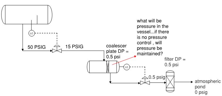
but incase i put a level control on water pressure vessel with continuous flow coming in and going out...will that help keep pressure at 15 psig...in this case there will be constant flow into and out of vessel. the water pressure vessel will be fully filled with level control ensuring that water pressure vessel is always fully filled with almost no vapor space.
downstream of water pressure vessel we have a filter and then water exiting to atmospheric pond


Capture8005_qp52bp.jpg
 
ok so it looks like you are trying to get any oil droplets out stilll remaining in the flow from the first vessel by sending through a coalescing plate oil removal system. I don't know what the internals of that vessel looks like. I imagine the oil that coalesces out is removed in a drawoff system pipe at top of the vessel. I would need more details. Is there a vapor space required in that vessel? Why would you need level control in that vessel. What are you controlling? The interface level of the oil and water? Seems like if any air intially in in the coalescer vessel it can be bleeded out just like a pipe at high point and then on there will be all liquid in vessel so no need for level control except maybe for oil/water interface control.

I believe in such a congfiguration you will need to design the coalescer vessel for maximum possible pressure pof the uptream separator. There may be very little pressure drop over the LCV 50/15 psig say if the valve is wide open if the level in the separator increases rapidly. So the pressure in the coalescer vessel could be about equal to the separator vessel in particular if the LCV of that vessel is stuck open.

It seems like all you would need is a LCV for the first vessel which will maintain level in that vesszel and let the flow be whatever it is without any further control through the coalescer and filter. However you may need some automatic air release vents on the coalescer and the filter. Then design the downstream vessel pressures for blocked flow.
 

Snickster - yes this pressure vessel is to remove any entrained oil. level control in this vessel is just to maintain an interface b/w oil and water. This pressure vessel will be full of liquid. Noted on ur point to design this vessel for the max op pressure of the upstream separator. But I am still trying to understand what pressure we will get in this vessel. If I keep the level control and say I keep its size for inlet pressure 15 psig and outlet at 0.5 psig and also I design the upstream control valve for p inlet at 50 psig and p outlet at 15 psig, will I more or less get 15 psig in this vessel. Will we see 15 psig here with out any other controls?
 
Zamakaze,

In this case you need to work from known values. The only two are the start pressure (50psi) and the end pressure (0 psig).

So in your diagram - and please stop drip feeding information, it drives people nuts - the pressure d/s the second valve is 0.5 paig

But if the pressure vessel is full of liquid it won't have a constant pressure as it will easily be anywhere from 50 to 1 psi dependency on the action of the control valves.

I think your system as drawn is not feasible and pressures will fluctuate all over the place.

Remember - More details = better answers
Also: If you get a response it's polite to respond to it.
 
I agree that your pressures will fluctuate between pressure in separator vessel to whatever the pressure drop is across the filter. The control valves are controlling level not pressure. You may be designing for a certain delta P across the valves which is correct but that does not control the pressure it only sizes the orifice of the control valve so that it is within a good operating range of the valve.

Look at the different scenarios that can happen with the control valves. Say that the level in the separator is rising fast so the LCV on that vessel goes wide open but at the same time the LCV on the coalescer goes closed if the oil/water interface is dropping. In this case the pressure in the coalescer will rise to pressure of the separator less the pressure drop in piping and control valve.

However I am not sure how the coalescer is configured. What happens to the oil drawoff? Is it discharged to atmosphere or to a pressure vessel at a set pressure? This will control the pressure in the coalescer along with the action of the control valves. Need full P&ID to understand what is going on.
 
Status
Not open for further replies.

Part and Inventory Search

Sponsor