Eng-Tips is the largest engineering community on the Internet

Intelligent Work Forums for Engineering Professionals

  • Congratulations waross on being selected by the Tek-Tips community for having the most helpful posts in the forums last week. Way to Go!

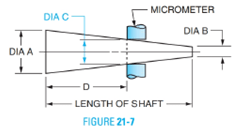
How to dimension male taper 1

Status
Not open for further replies.

310toumad

Mechanical
May 12, 2016
63
0
0
US
I have two parts that locate on conical tapers. Attached is the female taper, which they define by calling out the diameter at the narrowest location, followed by the angle. This part already exists and is not made by us. What would make the most sense in terms of where to call out the diameter on the male portion? Part of me thinks it should be called out at the same location that is shown on the female taper, so for the male this would be the "tip." However, I feel like this would be a difficult diameter for whoever is making it to inspect, so maybe it would be better practice to call out the diameter at the base of the male taper (there is an undercut around the base so there would exist a well-defined edge which to measure). Perhaps I could have the diameter of the female portion of the taper with its tolerance listed somewhere on the print as well as a reference?
 
 https://files.engineering.com/getfile.aspx?folder=c7b9a32f-4221-4136-bf70-6d9f507bb027&file=taper.jpg
Replies continue below

Recommended for you

That's a rather poor drawing. That is, you either define the diameters and the separation, or one diameter and the angle, and the length. Not all of them at once. Maybe the length, with no tolerance, is a reference dimension in which case it should be indicated as such.

Ask your inspection people for what they'd prefer.

<Late edit, I mistook the bore for a continuous taper, is the 10 the length of the taper?>


Cheers

Greg Locock


New here? Try reading these, they might help FAQ731-376
 
This is a common method of defining a tapered fit in machine tools. I think you might be misinterpreting the drawing. As I see it the minimum bore diameter is 74.4. The 74.997 indicates the diameter of the tapered surface at a plane 10mm from the outer surface. Obviously the male member will have a matching taper angle. At some point along the male taper it will have a matching diameter of 74.997. I would dimension the male member using that matching point. You dimension its angle anywhere. Then dimension the horizontal distance from a critical reference surface to the point on the taper at which its diameter is 74.997.
 
Reference:
html_98310-21-9a_image001_msvxu3.png
 
You fairly easily know the min and max dimension of the taper, the angle and the tolerance of the bores. The easiest way I see to inspect this is to drop the part on a taper with a dial indicator or indicators and measure that the length of the taper falls within the tolerances.

I admit I'm not up on using minutes and seconds for angles on dimensional drawings but I'm old.
 
Another point, and this one is functional, not dimensional. In my experience tapers of that short "aspect ratio" create more problems than solutions. The main purpose of tapers is to insure concentricity and alignment of rotating members. But to do that they have to be long enough to prevent angular variation. Notice all the drawings on line of Morse Tapers. They all show a long tapered member. There's a reason for that.

I have personal experience with the bad results of inexperienced designers thinking they are doing a good thing by including a tapered fit in an assembly of high speed rotating components. But because of space limitations they made the tapers shorter than they should have been. The assemblies involved were large shafts rotating at 1500 rpm with large rotary unions at each end. Those rotary unions mounted on those "short" tapers were very easily misaligned. The result was so much vibration the rotary unions were just blurs. We lived with that situation for years and went through thousands of dollars worth of ruined rotary unions and bearings until somebody identified the cause of the problem (short tapers) and fixed it.
 
Yes I see how the print is describing the part now. I guess because they showed the "gage" line as a solid line I thought that is where the taper terminated, but I see that is not the case. So in your reference picture, does the dimensions "D" to the gage line have a tolerance, or would it just be listed as reference?
 
You're the engineer. You are the one that knows how precise this whole thing should be for the application. You also are the one that has the best understanding of how variations in geometry may affect other factors. Its up to you to specify the tolerance. If you are indeed a newbie I would STRONGLY recommend getting the advice of a gray-haired mentor, or a machinist with a lot of scars from the years. They'll give you good advice.
 
Status
Not open for further replies.
Back
Top