feanalyst2
Computer
- Dec 20, 2022
- 4
Hi everyone,
I am trying to double check the direct stiffness method in Abaqus, for the contact between a rigid body and a linear elastic body.
What I have done is the following:
1) Create the linear elastic body, and extract its global stiffness matrix K in Abaqus as:
** Output Global Stiffness Matrix
*Step, name=Global_Stiffness_Matrix
*MATRIX GENERATE, STIFFNESS
*MATRIX OUTPUT, STIFFNESS, FORMAT=MATRIX INPUT
*End Step
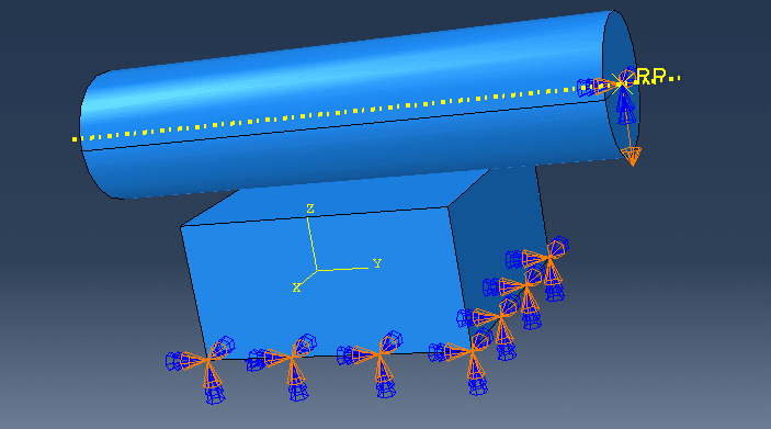
2) Add the rigid body, define the (frictionless) contact interaction and the boundary conditions (that is, prescribe the displacement of the rigid object to indent the soft body, and fix the soft body to the "ground"). See the figure.
3) Simulate the contact according to 2), by using NLGEOM=off.
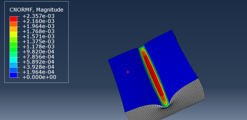
4) Extract the contact forces F_c (using CNORMF, see figure), the reaction forces F_r, and the displacements U.
5) Compute F_fem = K*U in Python.
I would have expected that, computing F_fem this way, I would end up with the forces corresponding to the contact surface equal to F_c, the forces corresponding to the ground BC equal to F_r, and zero forces everywhere else. But this is not the case. What am I missing?


