Continue to Site

Eng-Tips is the largest engineering community on the Internet

Intelligent Work Forums for Engineering Professionals

  • Congratulations waross on being selected by the Eng-Tips community for having the most helpful posts in the forums last week. Way to Go!

How to ensure plates in a hydraulic press remain perfectly parallel 1

Status
Not open for further replies.

grahamrigs

Mechanical
Oct 17, 2019
5
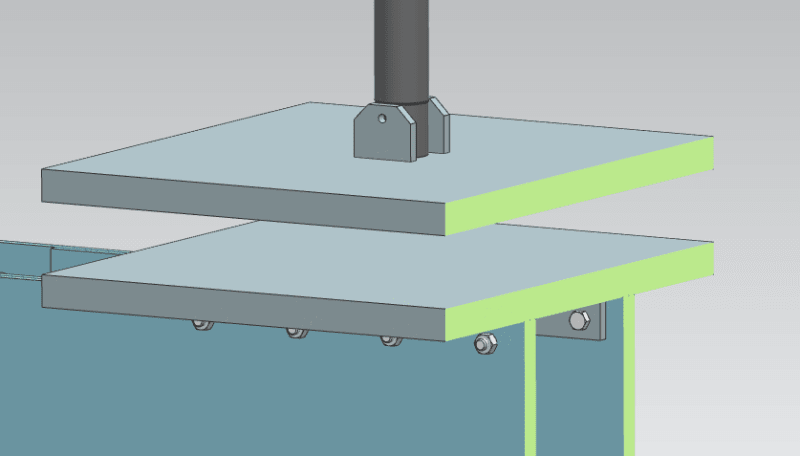
So I'm designing a test rig in a hydraulic press. This is the general overview, the green is a section cut view.
TwoPlates_eem99z.png


The bottom plate is firmly attached to mounting holes on the press. The top plate will be pushed downwards by the press, compressing a not-necessarily flat object between it and the bottom plate. I need to ensure that the two plates remain as close as possible to parallel throughout the whole range of motion, which is maybe only an inch or two.

The only method to attach to the press' ram is a single 3/8" hole through the shaft. I've quickly modelled up the above image by assuming the top plate is attached to the ram with this bolt hole, but this isn't necessary if alignment is handled in another way (in fact, this may be preferred).

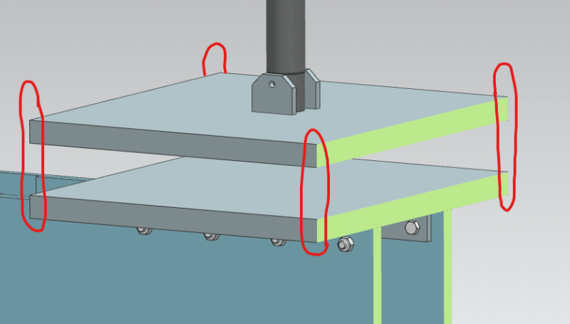
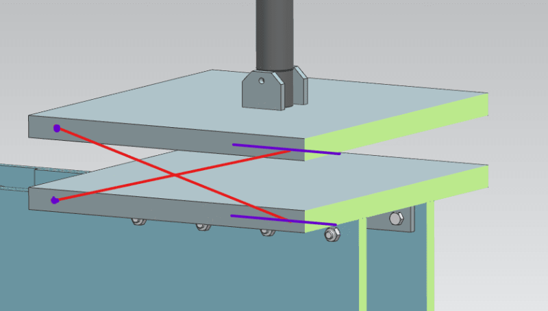
Just to kick off some ideas, here are small sketches of a linear guide system and a scissor system to ensure parallel.
TwoPlates_corners_b6n7lr.png


TwoPlates_scissor_q3cfft.png


Is there a simpler solution to this? The plates measure 24x24 inches (61x61 cm) and the press force will be up to 64 000 lbf (285 kN; equivalent of ~8 atmospheres of compaction pressure over the full area). These forces are within the capacity of the press, though barely.

Thanks for any help!
 
Replies continue below

Recommended for you

Why only one bolt? That automatically allows one degree of freedom.

Why not a tight-fitting collar that's welded in-place to the upper plate after the plates are mated?

TTFN (ta ta for now)
I can do absolutely anything. I'm an expert! faq731-376 forum1529 Entire Forum list
 
We already own the press and there's only 1 hole in the ram; I don't think I'd be allowed to go and drill another one, and I can't guarantee they would be perfectly vertical.

I guess one thing I didn't mention is that this fixture needs to be removable 100% from the press as it's used for a lot of things. All contact methods have to disassemble relatively easily.

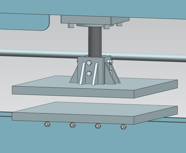
I kind of like your idea of welding a collar to the top plate when the two plates are aligned in the press. For removability, maybe it could be a loose collar with maybe 8 tapped holes for bolts that would cinch the ram, like a christmas tree base? It would be cinched up when setting up the machine just like the welding process would be.
 
Why not use a die set as in the four post unit pictured off to the right in the link?
 
What are you doing with the press? The simplest approach would to press to stops. The plates will end up parallel but not until they come to the stops. If the plates must be parallel at all times, you have the wrong press, because the whole press mechanism must be very beefy and robust to maintain parallelism.
 
@djhurayt

I didn't know about die sets before. It seems they're used to stamp items? Would they be robust and maintain parallel?

@compositepro

I'm creating a test rig whereby a component needs to be compressed between the plates at around 8 atm of pressure, while being forced flat if it isn't, and then perform experiments while it's under pressure. Yeah that's what I'm fearing, that the press isn't perfectly aligned. So I'm trying to come up with a way to ensure that it is aligned in setup or actively during runtime.


I mocked up the "christmas tree base" idea I had. Opinions on it? I figure that even if the press isn't perfectly aligned with its base, it will extend almost perfectly linear, so during setup this will account for any offset. Just need to tighten the screws enough. (btw, what is this sort of thing called?)

TwoPlates_clamp_lznsqv.png
 
The resistance and parallelism is a function of what is being pressed. If the material is of uniform thickness, uniformly covering the press surface, and of uniform properties then the press faces will remain generally parallel. If there is a tungsten block at one corner, the faces will not remain parallel.

To make progress on this one needs to understand elastic properties of the material to be pressed, the deflection of the parts of the press, and how much variation is allowed.

"Parallel" is a simplification that cannot be a design driver for this case.
 
You must define your parallelism requirements precisely and how off-center your loading can be. Then you can calculate how stiff your structure must be. But it looks like your current design will not be at all stiff against off-center loads.
 
Hi

You could just let the top plate connected to the ram float on a ball socket, it will then find its own position when under load.

“Do not worry about your problems with mathematics, I assure you mine are far greater.” Albert Einstein
 
To answer all your questions, I am not expecting perfectly parallel in all scenarios. It will be compressing fibre mats. The mats will be roughly flat already before compressing, roughly uniform at all locations, and be aligned in the centre of the test rig. So there won't be huge eccentric loading, but there will be some just due to the mat manufacturing process not being perfect.

As for degree of parallelism, my benchmark is if taking 5 thickness measurements of the mat at max load around the rig, then the standard deviation divided by the average should be less than 1%. Not a very easy value to understand, but that's the one I'm designing to.

I have looked into those die presses, but I haven't really been able to find one large enough? 2416-4C-1 in comes close, but still not quite as large as I'm desireing. Do they have a load capacity? I don't see one in the spec sheet.
 
Your fixture needs to be rigid and self-aligning, with force applied by a cantilevered cylinder I'm always careful to leave a bit of tolerance so the cylinder self-aligns. Commercially made die sets are often cheap and easy but if they're limiting you then simply buy hardened pins and bushings to make your own.
 
If you clamp the platen to the ram it will likely be subjected to some amount of bending.

Hydraulic cylinders have limits on the bending they are meant to endure.

Long ones with bronze bearings can handle a fair amount.

Compact Short ones with basic internal guides are rated to handle ZERO.
 
From Don56's link -
"Remember, guide pins are meant to align the upper and lower die shoes, not to align a poorly maintained or sloppy ram in a press! Some companies try to compensate for a poorly maintained press by adding oversized guide pins or grinding the guide pin ends to a cone shape. "

The OP's decription of his press, the hefty force applied, and the sole description of the unknown squeezed material as "not-necessarily flat" leaves me guessing that the eccentric forces on the ram could be severe.
In that case An asymmetrical array of Guide pins and their attachment to the upper and lower shoes would then also be subjected to powerful bending and jamming forces.

Look how easily a force applied 8" eccentrically bosses around a wedged tapered fit pin 1"Ø with L/D ratio of about .7.
7
 
Status
Not open for further replies.

Part and Inventory Search

Sponsor