Hi guys,
I have another CATIA problem I am hoping someone can help me out with:
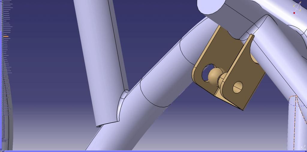
I need to do analysis on a complex weldment which is assembled from many parts. When the physical parts are assembled, they are jigged together which leaves gaps, the welder then fills these as he welds the assembly together. My issue is with modeling this, I cannot figure out how to create a fillet type feature along a seam where the parts do not fully intersect. Please see image below, where there are two different examples of the type of geometry I am having a problem with: 1) the sheet metal bracket is coped imprecisely to the tube, leaving a small gap that is filled with weld. 2) Typically tube-to-tube copes are similarly inexact, leaving area to be filled, one such is shown bottom left of the image.
What I would like to do is merge these parts into a single, contiguous solid which I can then treat as a solid 'chunk of metal' for purposes of meshing and static analysis. I would then assemble this 'chunk' component to a couple of other similar ones with appropriate boundary conditions, and run the analysis on the whole assembly. Obviously I am not super experience with FEA, and what I have done was mostly in ANSYS, which I don't have access to, so I am a little out of my depth as this is not something my job often requires.
My question is, since I already have each component modeled based on actual geometry and constrained in an assembly, is there an easy way to connect all these seams as one would do in real life, or do I need to create new models which are "ideal" representations of the parts that all fit perfectly enough that they can be combined into a single solid?

What I have tried so far:
1) Weld Design Workbench: Cannot define a fillet weld on complex geometry.
2) Generate Part from Product, then Add all parts into one solid, fillet edges. This works for parts that fit perfectly, but not for the examples above. Face-face fillet doesn't work either. The only thing that I can get to work is 'Styling Fillet' in GSD, but the surface it creates is not bounded properly to be able to add thickness and make it into a solid.
3) Export as .stp to Solidworks to fix it there: Solidworks has issues with the geometry on import, and I'm not sure I could fix it in SW anyway.
What I have not tried:
- Project line from part A to B, create a boundary, do a surface fill, then add thickness and merge into solid. I think this would work but it would take so long to fix every issue that I might as well redraw the whole assembly.
-Redrawing with 'ideal' geometry so everything fits perfectly. I considered this, but it isn't how we receive the parts, and this assembly has ~300 parts, so it would take a lot of time.
- Leaving the model as-is and fixing the gaps by manipulating the mesh in Analysis workbench. I suspect this might be the solution, but am not that familiar with GSA to be confident I can figure this out.
Anyway, it seems like this has to be a common enough problem when working with welments, so if someone else can tell me the best approach it would be much appreciated!
Thanks,
Pat
I have another CATIA problem I am hoping someone can help me out with:
I need to do analysis on a complex weldment which is assembled from many parts. When the physical parts are assembled, they are jigged together which leaves gaps, the welder then fills these as he welds the assembly together. My issue is with modeling this, I cannot figure out how to create a fillet type feature along a seam where the parts do not fully intersect. Please see image below, where there are two different examples of the type of geometry I am having a problem with: 1) the sheet metal bracket is coped imprecisely to the tube, leaving a small gap that is filled with weld. 2) Typically tube-to-tube copes are similarly inexact, leaving area to be filled, one such is shown bottom left of the image.
What I would like to do is merge these parts into a single, contiguous solid which I can then treat as a solid 'chunk of metal' for purposes of meshing and static analysis. I would then assemble this 'chunk' component to a couple of other similar ones with appropriate boundary conditions, and run the analysis on the whole assembly. Obviously I am not super experience with FEA, and what I have done was mostly in ANSYS, which I don't have access to, so I am a little out of my depth as this is not something my job often requires.
My question is, since I already have each component modeled based on actual geometry and constrained in an assembly, is there an easy way to connect all these seams as one would do in real life, or do I need to create new models which are "ideal" representations of the parts that all fit perfectly enough that they can be combined into a single solid?
What I have tried so far:
1) Weld Design Workbench: Cannot define a fillet weld on complex geometry.
2) Generate Part from Product, then Add all parts into one solid, fillet edges. This works for parts that fit perfectly, but not for the examples above. Face-face fillet doesn't work either. The only thing that I can get to work is 'Styling Fillet' in GSD, but the surface it creates is not bounded properly to be able to add thickness and make it into a solid.
3) Export as .stp to Solidworks to fix it there: Solidworks has issues with the geometry on import, and I'm not sure I could fix it in SW anyway.
What I have not tried:
- Project line from part A to B, create a boundary, do a surface fill, then add thickness and merge into solid. I think this would work but it would take so long to fix every issue that I might as well redraw the whole assembly.
-Redrawing with 'ideal' geometry so everything fits perfectly. I considered this, but it isn't how we receive the parts, and this assembly has ~300 parts, so it would take a lot of time.
- Leaving the model as-is and fixing the gaps by manipulating the mesh in Analysis workbench. I suspect this might be the solution, but am not that familiar with GSA to be confident I can figure this out.
Anyway, it seems like this has to be a common enough problem when working with welments, so if someone else can tell me the best approach it would be much appreciated!
Thanks,
Pat