Eng-Tips is the largest engineering community on the Internet

Intelligent Work Forums for Engineering Professionals

How to find the Max capacity of the foot bracket using FEA? 2

Status
Not open for further replies.

imti7

Mechanical
Jul 19, 2023
50
0
0
IN
Hi ,someone please help me to get the capacity of a foot bracket
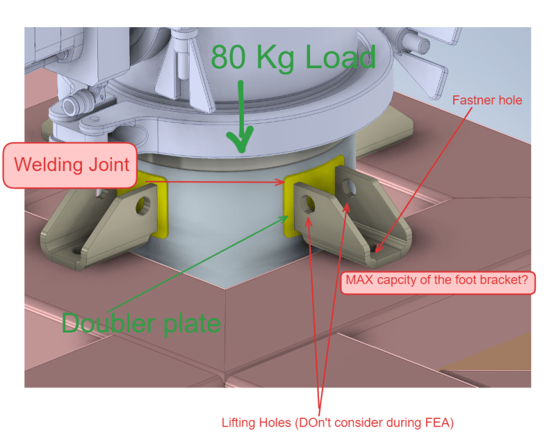
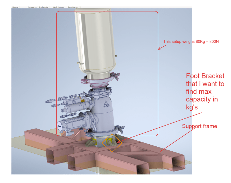
Objective : Find max capacity of the foot bracket(please refer the image for more details)
total bracket carrying load : 800N (80kg)
Softwares i use for FEA : Inventor & Solidworks

As i'm a designer , i'm not much involved in FEA before , please someone help me to find the capacity of this bracket
1. I don't know how to apply loads for this criteria and read the results of FEA like von mises stress contour plot and get the capacity, please explain me ?
2. I have attached the STEP files too
Screenshot_2024-05-20_173422_ewagwy.png

Screenshot_2024-05-20_173459_uh6g6z.png


Kindly find the link to STEP file :
 
Replies continue below

Recommended for you

I'm sorry, but "no".

You don't know enough to appreciate what you're doing. Brutal, but I think it's true.

If you want to learn FEA, start with the examples in Inventor.

But if you really want to learn, it'll take a lot of work, and Inventor is not IMHO a good code to learn with. It has been "optimised" so that designers can quickly create pretty pictures.

"Hoffen wir mal, dass alles gut geht !"
General Paulus, Nov 1942, outside Stalingrad after the launch of Operation Uranus.
 
I agree with rb1957.

You want to check the bracket.
The connection between the bracket and the doubler plate is basically two rectangular sections, since the horizontal part of the bracket does not meet the plate. That means that a hand calculation is probably sufficient for that section. The only reason I can see that motivates using FEA is the holes, and they should, for some reason, not be considered.

I think you need someone who can guide you in this.
 
If you are not familliar with FEA which is evident from point 1 you mentioned, its better to pass this on to qualified FEA analyst in your organization.

One thing you can do is analytical calculation as a designer for this bracket and find out analytical capacity using mechanics approach.
 
Thank you so much for the response
Yes , I agree i'm so noob in FEA, but i would appreciate if you guys can give me some sources where i can study well the basics, i went through many videos in the youtube but those aren't helping much

or if you can please perform on this one and let me know the steps, it would still be great for me to understand practically.

I give all the information required like
Material : SS304
Boundary conditions : Fixtures
whatever it is necessary.

Please guide me through🙏

Thanks once again for looking on my problem
 
imti7 said:
but i would appreciate if you guys can give me some sources where i can study well the basics

I would recommend "Practical Finite Element Analysis for Mechanical Engineers" by D. Madier for a start but there are also many other good resources and what really matters is a lot of practice.

imti7 said:
or if you can please perform on this one and let me know the steps

Start by reducing this huge assembly to just the bracket that you want to analyze. Think about how it should be supported and loaded considering its interaction with other parts. Then add only the parts to which this bracket is attached and replace the rest with a remote mass/load and see if you get similar results.

 
imti7,
FEA is just a fancy tool that can be dangerous.
You should be able to analyze the bracket using classical hand analysis methods; its not that complicated. You need to start by drawing a free body diagram (fbd) of the bracket. Then make a list of all of the potential failure modes of the bracket. Then list the analysis checks for each mode.
If you can't do the above then sorry to be blunt but you have no business in attempting any sort of FEA.
But if you show your fbd and failure modes and analysis list here we might be able to guide you a bit (use the image button).
 
I would start with the Inventor manual, or YTs.

I have little problem with designers running some analysis to check their sizing. In the olde days, designers could design by eye and get pretty close. Also today, when you have sufficient experience. Designers should not IMHO be FEA specialists, they have their own body of knowledge to worry about, as we have ours. IMHO, your effort in modeling should be little more than meshing the CAD part, simple constraints, simple loads, and nice looking picture. But don't expect the stress guy to say "great, my job is done". There is a lot in FEA ... it is a deep, dark, hole.

"Hoffen wir mal, dass alles gut geht !"
General Paulus, Nov 1942, outside Stalingrad after the launch of Operation Uranus.
 
imti7 said:
or if you can please perform on this one and let me know the steps, it would still be great for me to understand practically.

If you read my post you will see that I mentioned a hand calculation, start with that and compare it with a similar FEM-model.

If you for some reason don't know how to do the hand calculation, skip FEA and start learning the basics in mechanics. FEA can be a powerful tool, but it can also be a "black box".
 
I see two potential hurdles for you to cross to get to a correct answer:
1) Stress analysis (strength of materials) - were you trained in this? If you haven't taken this coursework then you really shouldn't use FEA until you have mastery of that subject using traditional calculations. Full stop.

2) FEA (Finite Element Analysis) - I can see you're not training in this either. I learned FEA outside of college but it took me some years, some caution, and having my models reviewed by a more senior colleague before I considered myself competent. It's a software that will have you making pretty color pictures quickly, and correct results much later (if ever, depending on the guidance you receive).

FEA is a rabbit hole. Not a bad one, just a big one. There are many who take a Masters focused on this subject alone.

Inventor-Nastran performs FEA and for simple cases, does a perfectly acceptable job of it. It also keeps your FEA model linked to your parametric CAD model, so you can adjust the design quickly based on the FEA results. The trouble is knowing what is/isn't a simple FEA case, and whether the FEA solution is accurate.
 
Status
Not open for further replies.
Back
Top