Continue to Site

Eng-Tips is the largest engineering community on the Internet

Intelligent Work Forums for Engineering Professionals

  • Congratulations KootK on being selected by the Eng-Tips community for having the most helpful posts in the forums last week. Way to Go!

How to improve the load carrying capacity of an existing RCC slab deck bridge 9

Status
Not open for further replies.

D.Jaya

Civil/Environmental
Sep 11, 2017
29
How to improve the load carrying capacity of an existing RCC slab deck bridge

I am seeking an advice from Engineers having experienced in bridge design/bridge construction, who are members of this forum

There is RCC slab deck bridge is at a rural village area in Liberia (western Africa) We are doing a mini Hydro electric project at a nearby Village and our heavy machinery etc to be transported over this bridge once we receive the shipment.
We don’t having the values of loadings where the bridge has been designed for or any other structural details related to this RCC Bridge. So we don’t having a proper idea whether can it withstand the loading of heavy equipment during transportation to the site. (Our heaviest equipment to be a electrical generator which the load is about 7Tons + transporting vehicle weight(Low bed)
I am a structural Engineer with design experience related to buildings. Our management, who is the contractor for the mini hydro project want me to prepare a report to the owner regarding the improvements (where necessary) to strengthen this bridge and other roadside structures (such as RCC culverts)I can provide solutions for the RCC culverts but I am having no proper idea about how to strengthen(If necessary) the bridge.
The said bridge 22 m long having 02 spans each 11.0m in length and with a central Pier and two abutments. Slab deck thickness to be about 250mm.Also Gr: 30 concrete to be assumed has been used .It can assume that the bridge has been constructed about 15 years ago. So far the structure is functioning without visible defects.
My proposed strengthening arrangement(02 steel beams will hang from steel girders and the end of the girders to be rest on additional concrete footing or an existing pier extension as shown (Ref to the attached sketch)
Please comment on the following

1)If I were to design for the additional supporting(steel members)for an extra loading, can we assume what percentage of the total loadings to be taken by the additional supporting structure

2)Can I assume that the additional Steel Beams in between the 11 m span (of 11/2 =5.5m ) to take the loading from the deck as a Simply Supported beam

3)please comment on the ways related to improving Punching shear resistance for the RCC bridge deck
4)Pl. suggest any other suitable strength improvement scheme regarding this bridge & any literature sources etc.
(Also please note that this arrangement will provide a solution to function the bridge for the traffic during the construction work (related to strengthening). There is no way to build intermediate Piers due to the river flow and also the strengthening work to be done in a shortest possible time duration


 https://files.engineering.com/getfile.aspx?folder=a556d577-611c-4847-ba05-cf2e6ecf8421&file=Bridge_Drg.pdf
Replies continue below

Recommended for you

I have lots of experience with bridge design and lots with bridge strengthening, retrofitting, and load ratings. A 250mm thick slab spanning 11m is a pretty tall order. 7 tons is not that much, however. Can you please send the axle layout of your transport truck? Is there a joint in the slab over the pier? (i.e. is there any continuity across the pier or is it 2 simply supported elements?) I'm not sure what Grade 30 concrete is...

My typical order of events would be: Send field Engineer out to perform ground penetrating radar scan of soffit of bridge and come up with rebar spacing and approximate size. Run quick hand analysis to see if it comes out. If it does, you're done! If not but it's close and I feel confident that I can get it to come out with a more refined analysis, I will run a full 3D FEA analysis with shell elements and a moving load tracer to get better results on load demand. If it comes out, then you're done and the client is happy. But if it doesn't come out, the client is not going to be very happy if they paid you an extra fee to run the in depth analysis only to be told that they have to strengthen the bridge in the end. So you need to have confidence that you can get it to work on on paper in order to justify this additional fee.

If the client does not want to go this route, strengthening is the only other option. Your scheme requires abutment work. That is expensive. Can you shut the bridge down for any duration of time? What if you ran the longitudinal beams over top the deck and put 25mm thick steel plates over top those for a temporary deck? Essentially, the beams would float over the bridge and be supported only at the abutment and pier locations. This would require some partial closures and would require some regrading at the approaches to ramp the road up to the temp. bridge elevation...

 
D.Jaya said:
So far the structure is functioning without visible defects.

There is some information you can obtain... details on the vehicles that are successfully using the bridge, for example, weight and wheel spacing. This will at least give you an idea of what the existing bridge can support... not a good place to start, but better than guessing.

Adding a support in the middle of a simple span (making it two-span-continuous) is not a good idea, the added support will cause negative moments in the deck when loaded. A simple span would not have reinforcing steel located correctly for this situation.

[idea]
 
STrctPono said:
I'm not sure what Grade 30 concrete is...

Grade 30 MPa compressive strength concrete (say 4,000+ psi). OP may also be referring to cube strength not cylinder strength.

The rest of the world does not use Pagan-units (those pesky imperial units) :)
 
I still use them... and convert most of my work to Imperial to make sure I understand them... just too old...

Rather than think climate change and the corona virus as science, think of it as the wrath of God. Feel any better?

-Dik
 
Since you will have to lift the 14,000 lb.f off the transporting vehicle (low bed) at its final destination - presumably with a mobile crane - and presuming that such a crane would have to also transverse the same bridge, is it possible to have two cranes - one crane on each side of bridge? Crane 1 (located on side 1 of the bridge) picks and lowers the generator on bridge slab deck over the central pier (11m + pick). Then Crane 2 (on side 2 of bridge) picks up the generator from slab deck over central pier to side 2 of the bridge on the awaiting low bed for transport to project site. Place timber dunnage (as required) to slab deck over the central pier to distribute the generator weight. This assumes the existing UNstrengthened bridge has sufficient capacity for a mobile crane to traverse - which may be a big assumption, and hence requires verification.


Dear StructPono,SlideRuleEra,Ingenuity and dik
Thanks a lot for your valuable opinions and comments
 
If you have access to some crane mats or something similar, you could gain some significant capacity through increasing the distribution width and length of the load, or the more robust approach suggested by STrctPono.

Another, more permanent option, could be adding effective depth through the use of a bonded concrete overlay.

It would seem the first order of business would be to assess the current capacity of the bridge. If there's history for some heavy vehicles traversing it, as SRE said, that could help alot. If you don't have scanning equipment or history available, chipping some concrete off the bottom of the slab to find the size and spacing of the reinforcing, may be your next best option.

Of course, the best option would be to find the as-constructed plans for the bridge. I would make my best effort to get ahold of them.

It may be stronger than it would appear. The load distribution characteristics for slab bridges are very good, considerably better than traditional analysis indicates. So if it's not really narrow, and traditional analysis shows it's inadequate, but not failing miserably, an FEA could show it works without strengthening. We've seen capacities as much as 30% higher with FEA vs. traditional methods.

Rod Smith, P.E., The artist formerly known as HotRod10
 
It seems to me this is a 1st world solution to a 3rd world bridge.

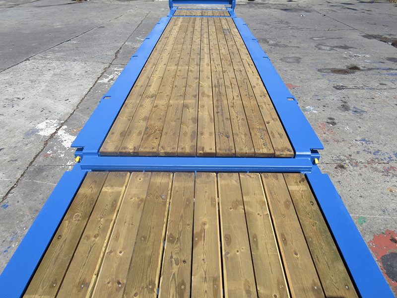
Why not just lay two containers end to end on the bridge ( 12.2m long), pin the doors back or take them off and then just drag the generator through them or on the back of a small vehicle not as wide as the container?? That would span the bridge between your support points??

Or get two fixed flat rack containers and chop the ends off or lay them flat as ramps. they have the loading for p to 25 tonnes capacity.

image_lsth8c.png


Or hire a bailley bridge?

Many many ways to skin this cat.

Remember - More details = better answers
Also: If you get a response it's polite to respond to it.
 
BridgeSmith (Structural)and LittleInch
Thanks for your thought provoking Opinions.....

 
D.Jaya:
Problems like this seem overwhelming when they are first trust upon you, and the more so, when this area of engineering practice is kinda new to you. But, you start be putting one foot in front of the other. Ask yourself what info. do you need to even get started, understanding the magnitude of the problem, rather than all the guessing we are doing here, so far. Where is the best place to get that info., and pick two or three, in order, since the first one might not want to be particularly helpful without some incentive or remuneration. You are doing this to improve the lot of the locals, or some local industry, I assume, and I would play this card in asking for some basic help from them. It’s the old…, why should I waste my coffee break or dig a little deeper in the files to help you, what’s in it for me? It’s good for your team, in country, to nurture these kinds of relationships, you will need them many times on the project, not just this bridge rating problem.

You have an awful lot of prelim. investigative work to do before you can start honing in on this particular question. I would assume that you have some people in country who could be of much help in gathering some of this info., that is a good part of what they are there for during the early stages of the project. They might go to the local authorities for info. on that bridge, plans, specs., calcs., etc. from their roads/bridges dept. Who was the original contractor on the bridge, do they have the needed info.? Is this a goat path or a real light highway bridge, and what max. loads use it now? Do you have to work around existing guardrails, end/wing walls and the like for clearances and bridge strengthening. Will the center pier, the abutments and bearings take the max. loading you intend to apply? Get a bunch of good pictures of all of the bridge details, etc., this will tell you something about the bridge condition and quality of its construction. What is the makeup of these 23’x36’x10” deck slabs, and are there longitudinal girders under the deck slab or does it actually span 36’? Make a list of all of the large loads to be transported from port to site (from your purch. dept.), and the trailers and tractors to be used for the transport, axle spacing, max. wheel loads, etc. You will need this list again for ongoing lugistics. Actually, the worst loads on the bridge might be ready-mix conc. trucks and large dump trucks, crane transport, or other construction material transport trucks, since 14tons is not a very large load. While the generator might be the largest/heaviest piece of electrical equip., transformers and turbines and the like will be in the same ballpark. As mentioned above, some 36’ long stl. bms. and some wooden crane mats might be your basic go-to materials for this bridge deck and the culverts, as a means of load sharing and load distribution. Much of this should be rental materials/equip. from a good rigging and heavy hauling contractor, maybe from or finally into their own inventory of equip. Curves onto and off of the bridge could add to clearance problems.

 
dhengr,

A great post and very sound advice on the process to use.

The other aspect to all of this in remote places is how do you get in there to build any of the reinforcement. Those steel beams will need cranes - are there any locally big enough?

The vehicle you transport a 7 ton piece of equipment on, if it is indeed a low loader, could weigh 14 tonnes on its own.

But use of lots of 10 tonne trucks could damage the bridge even more than one slightly heavier load.

All this boils down to risk assessment and the appetite for risk by your management and owner. Nothing is risk free or it would cost 10 times the amount.

Risk free is build a new bridge using design and materials you have confidence in.
Acceptable risk is doing something along the lines of what we've suggested and you've looked at.

Personally I don't think adding some point supports to a slab you know nothing about is going to reduce your risk enough to make it worthwhile. Adding some strength to the slab and assuming the supports are going no where seems a better use of your time and money, IMHO. Even if the supports subside a bit, nothing should fall off the bridge. Break the slab and the whole lot could go.

and include some monitoring of the structure on a regular basis, especially after any heavy rain.

Some pictures would help a lot....

Remember - More details = better answers
Also: If you get a response it's polite to respond to it.
 
dhengr(Structural):
Thanks for your lengthy reply....I got a good insight about the problem and got an idea about what information required to tackle this problem
LittleInch (Petroleum):
Thanks for your opinions
 
No problem. You're doing a good thing and I hope we've all helped in giving you options to consider.

Please let us know what you did in the end, even if it's in 3 months time. It's always great to get feedback and see what happened.

Good luck.

Remember - More details = better answers
Also: If you get a response it's polite to respond to it.
 
Status
Not open for further replies.

Part and Inventory Search

Sponsor