Continue to Site

Eng-Tips is the largest engineering community on the Internet

Intelligent Work Forums for Engineering Professionals

  • Congratulations GregLocock on being selected by the Eng-Tips community for having the most helpful posts in the forums last week. Way to Go!

how to increase footing thickness? 3

Status
Not open for further replies.

abdallah hamdan

Structural
Oct 13, 2021
32
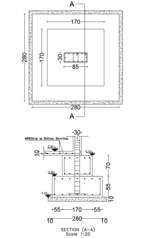
Hello everyone, I have a Footing that was poured at 55 cm thickness, 15 cm lower than required (70 cm), punching shear failure will occur, How is it possible to increase the thickness of the footing?
note that the footing was poured recently, and no work has been done on the column necks
any ideas
thanks in advance
 
Replies continue below

Recommended for you

If actual poured concrete strength is significantly higher than design, can you take advantage of that?
 
Can you splay out the bottom 12 to 18-inches of your column to increase the shear perimeter, like an inverted column capital?
 
I don't see how enlarging the footing helps. You reduce bearing pressure but increase tributary area, so for pure vertical loads nothing has changed. If the footing takes lateral loads, this would help but that wasn't clear in the post. By inspection, flaring out the column base will solve the issue. You have say ~75% of the design capacity, so you building a column capital that pushes the one way shear failure plane out ~25% of the way to the edge and the problem is solved.
 
Maybe if the concrete strength is higher than required would help , but the concrete strength always came between 1.05-1.15 from required strength, that increase did not help

Can i make column capital or a footing increase in thickness , this is the question, it will not break ? As Its poured separated from the footing
 
canwesteng said:
You reduce bearing pressure but increase tributary area, so for pure vertical loads nothing has changed.

Not sure I agree with you there. I believe the OP clarified they were failing in 1-way shear.

For flexure and 1-way shear: Yes, the tributary under the footing increases but due to the reduced bearing pressure it doesn't mean it's a wash. It should drop the utilization.

The 2-way shear utilization may increase a little...
 
Bearing pressure decreases linearly with footing area, footing area increases linearly with footing area going up. The one way shear is equal to bearing area time bearing pressures, so an increase in area won't reduce shear. In fact, it bumps up flexure, with intuitively makes sense - a tiny footing the size of the column would have essentially no bending, at the cost of huge bearing pressures.
 
Yes sorry, I said that incorrectly before.

Flexure will increase in the footing... but the 1-way shear will drop in utilization with the increase in bearing area for the footing.
 
[highlight #FCE94F]Yes, the tributary under the footing increases but due to the reduced bearing pressure it doesn't mean it's a wash. It should drop the utilization.
[/highlight]
Noticed that I didn't say the applied 1-way shear decreases... I said the utilization decreases.

8ft x 8ft x 14" square isolated footing with an applied DL=50k from a 12"x12" concrete column.

Factored soil load for strength design of footing
Pu = 50K x 1.4 = 70k
qu(soil) = 70K/64ft² = 1.09375 ksf

One way shear:
Vu = qu B (L/2 - c/2 - d) = 1.09375ksf x 8ft (4ft - 0.5ft - 11/12) = 22.60k
ΦVc = 2Φbd √f'c = 2*0.75 x 96 x 11 x √3000 = 86.759K
Utilization = 26%


10ft x 10ft x 14" square isolated footing with an applied DL=50k from a 12"x12" concrete column.
Factored soil load for strength design of footing=
Pu = 50K x 1.4 = 70k
qu(soil) = 70K/100ft² = 0.700 ksf

One way shear
Vu = qu B (L/2 - c/2 - d) = 0.70 ksf x 10ft (5ft - 0.5ft - 11/12) = 25.08k
ΦVc = 2Φbd √f'c = 2*0.75 x 120 x 11 x √3000 = 108.44K
Utilization = 23%
 
is it possible to add a footing on top of the existing one, which will do its job to overcome one-way and two-way shear failure, while the existing footing will transfer the load to the soil safely?
121_t0l5jc.png
 
That looks like it would work.
If you have that much space then why not get the contractors to scabble the surface, epoxy some bars in, and pour a block the same width as the whole foundation below?

There are a few things to consider though
1) Make sure you have enough bar length in the right locations to be able to achieve all your necessary laps
2) Is this a seismic system? The sketch you've just shown has big implications in terms of where lateral loads are resisted within that column, the stiffness of the column, potential ability to hinge and so on. This will affect wind too of course but is a lot less important typically than it would be for a seismic system...if it's seismic then they should probably just demolish and rebuild
 
I've done your scab solution. In my case, we were adding load to an existing foundation (about +10%). The existing footing was an 8ft wide continuous "grade beam" footing. We drilled vertical bars into the top of the existing footing, and added an 8ft square "scab" on top to justify engaging a larger area of the existing grade beam. Checked vertical shear at the critical sections and checked the interface for horizontal shear (VQ / It) in the vertical dowels.

The shear wasn't that hard. The trickier part was how to get the load from the column into the top "scab". In your case, I take it the column hasn't been poured yet? So you may not have an issue there.
 
If it's not too big a footprint put vertical dowels in spaced as shear reinforcement and put a capping thickness on top. This is similar to one of the ways you do post installed shear reinforcement for seismic design in beams or slabs.

Footing on top of a footing that some people have proposed is fine too, but looks a bit wonkier.
 
How to add shear reinforcement do you have any photo or detail ?
and if i want to make a footing on top of footing what is the bearing capacity that i must design the top footing for ? I saw many bearing capacity equations for concrete and can’t understand how bearing failure is going to happen in material such as the concrete
 
abdallah hamdab said:
demolish and replace is the first solution but we need more time and a cost-effective solution,...

Demolish and replace is the cost-effective solution. You noted you have not placed the column yet in the the 3-days you've spent exploring other options you could have just bent the column dowels over as Hokie66 suggested and crane lifted the junk foundation out of the hole, procured new bars and potentially already placed the proper size foundation.

Every other option is very likely going to require more labor, more concrete, and more reinforcement and be inferior to replacement at this stage.
 
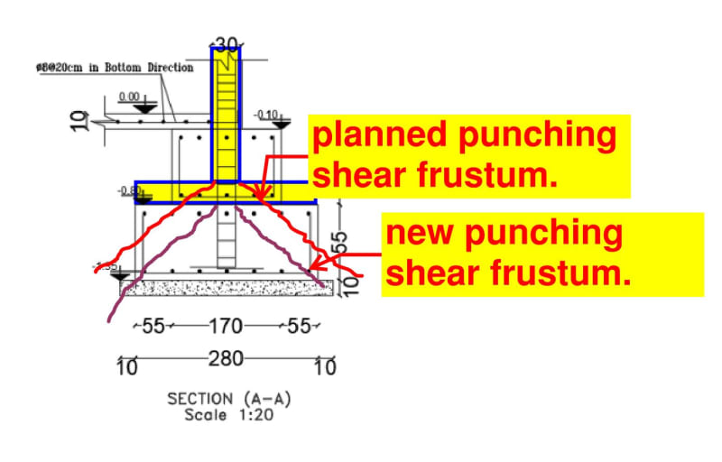
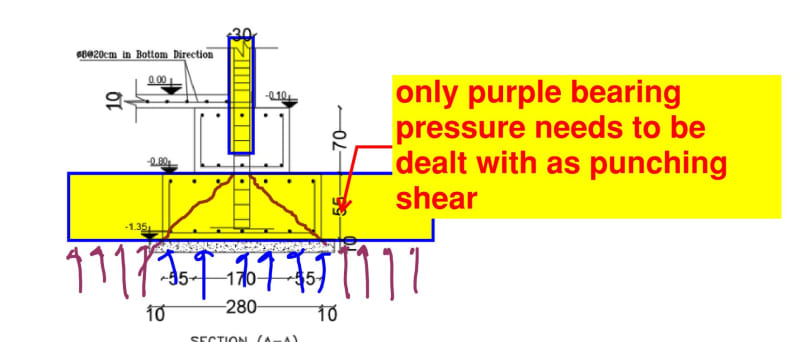
I'm not sure that there's actually anything here in need of fixing. It appears to me that your original punching shear frustum wouldn't have even been contained within the original footing. Looking at the proportions involved, I don't see punching shear being a legitimate failure mode for either the original design or modified condition present in the field.

If this thing even needs flexural rebar, it's basically just a strut and tie situation for an elephant's foot / pedestal element.

c01_j6pari.jpg
 
Ugh... I see now that OP's sketch was not to scale.

Depending on how the original design was performed, this might represent another path to "do nothing".

c01_nbnjgy.jpg
 
Further into the thread I think it's clarified that this is a one way shear problem. That being said, the code one way shear provisions are conservative for this type of deep beam situation with a short span. If it's failing out of the near field zone there are a couple of ways to take advantage of that conservative situation. One is a strut and tie model. The Canadian concrete handbook has this exact situation demonstrated in the examples, with a deep footing failing with the code provisions and then an example strut and tie model passing it.

The other option would be to go outside of local code to one of the codes that has more in depth provisions for shear near supports without strut and tie. The british code for instance has magnified shear resistance near supports that decreases as you move away. (edit looks like eurocode does something similar, but by reducing the design shear demand within a couple of 'd' distance from the support... also I'm assuming your local code is US based because you're using kips, but your drawings are in cm, so I'm not actually sure)

There's also some stuff you could potentially do with increasing bearing pressures in coordination with the geotech, but how comfortable I'd personally be with that depends on the loading conditions this thing is under and what the failure mechanisms would look like.
 
Status
Not open for further replies.

Part and Inventory Search

Sponsor