Continue to Site

Eng-Tips is the largest engineering community on the Internet

Intelligent Work Forums for Engineering Professionals

  • Congratulations waross on being selected by the Eng-Tips community for having the most helpful posts in the forums last week. Way to Go!

How to level a platform on top of a rod while using a coupling to attach the platform to the rod? 1

Status
Not open for further replies.

stuckagain

Mechanical
Dec 24, 2020
5
Hello all! I am trying to design some parts with CAD and am 3D printing them to test in advance of production with metal materials. I have vertical rod that will oscillate and am affixing a platform that will hold certain masses. The masses will oscillate with the rod and needs to be level. The levelling may shift over time or by location of the machine, so would like it to be relatively easily adjustable. Here is what I have so far:
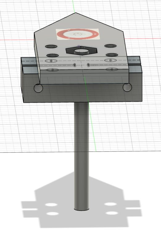
Pivot_Coupler_gyrkdh.jpg


The top "arrow" platform is separate from the coupling on the bottom. The coupling will fasten to the rod through the 2 holes on the side using nut and bolts. The rod will extend to the top of the platform such that it is not higher than the platform. The rod is threaded. I imagine the coupler will have 2 holes on the top of each side that can extend through the top platform (but should again not extend past the top of the platform). Those holes can also be threaded if needed.

I feel like there should be some type of screw that can be used / designed that can both fasten the coupler to the arrow platform and also adjust its level - but need some help on how to achieve. Any ideas?

Thanks!!
 
Replies continue below

Recommended for you

Level relative to what? Fitting your coupling with a slight interference will make it perpendicular to the rod so as long as the rod is in alignment your coupling will be too.

Otherwise, attach your platform to the coupling with bolts and use shims to level it. Using 3 bolts eliminates the soft foot which will make leveling easier vs. 4.
 
Hello TugboatEng - thanks for looking at my question. Sea level through the use of a circular bubble level. I thought about shims - but that is not easy to adjust as the part changes locations etc...
 
Hydtools- thanks. Looked this up and understand the concept. Now have to figure out how to design this screw part. I imagine some sort of mechanism that will have a space between my coupler and top platform. And at the same time how to keep tension such that the platform and coupler are fastened. I’m thinking maybe some locking washers or something. Interesting puzzle. Or maybe I am over complicating it in my head.
 
I interpret (guess) that "oscillation" is the rod rotating around its axis.
How violent is the "oscillation" ?

Is the image showing the rod as nominally vertical, and the face of the platform what needs to leveled?

What is happening to the lower end of the rod ? Could the leveling be better done there?
If so, The platform and coupling could be simpler.


Is the level correction to be done manually, every now-and-then ?
 
Hi tmoose,

The oscillation I would say has periods ranging from 1.5-2.5 seconds at the outer ends. Average is probably 2 seconds. Min/max rad/s is probably +0.9 to -0.9.

Yes the rod is vertical and the platform is what needs to be leveled. And will be leveled from time to time. I have less control over leveling the whole system and that’s why I am trying to adjust leveling between the coupling and platform.

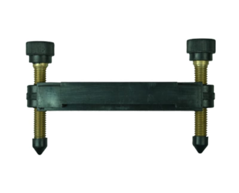
Anyone have the schematics for the screws that are in your second image ( or in the surveyors transit as suggested by hydtools? Maybe that will help. But still need to ensure everything is fastened together tight with no give.
 
Just use three turnbuckles...

The problem with sloppy work is that the supply FAR EXCEEDS the demand
 
hydrolastic suspension ... have the platform float on a fluid ?

another day in paradise, or is paradise one day closer ?
 
If maintaining level during oscillation is not the aim, simply use a rod with threaded end, screw and lock both the platform and the coupling to the rod. As long as the rod is plumb, the platform is level.
 
As is nearly always the case, defining the objective and "boundary conditions" etc, should be the first step.
I wonder if (hope) the OP did that before undertaking the design, but simple neglected to include them for us in the OP.
 
Thanks all - got some interesting ideas from this discussion, namely how the surveyor's transit is leveled and the idea of the jack bolts. I will try to model some of this up and see if it works for me - otherwise may poll the group for some additional ideas!
 
2015-03-23_18.01.21_m5rvrk.jpg

2015-03-23_18.01.35_tu40cg.jpg

2015-03-23_18.01.59_tw2chn.jpg

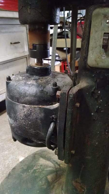
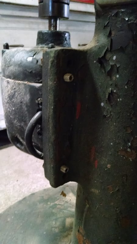
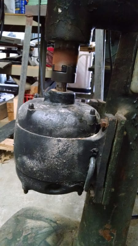
I found these photos from one of my old woodworking tool.
The motor is aligned to the shaft coupling by tightening and loosening the bolts and set screws.
 
Status
Not open for further replies.

Part and Inventory Search

Sponsor