Situation:
I have an assembly made up four layers of different material laminated together, the resultant thru screw clearance holes are toleranced like this:
Datum A is the flat bottom of the plate (perp to the thru holes)
Datum B is a locating hole pep to A
Datum C is a slot aligned with B and perp to A
I have created a functional gage to check the 10 thru holes sized at 0.152" + (extra to account for gage stack up)
The four layers are often shifted relative to each other, resulting in a "tilted" thru hole
The assembly sometimes fails GO/NO-GO gage check at the small size
The assembly usually passes the functional gage check
Lets assume that the holes in the four layers are at the maximum size and the relative locations are assembly process limited
Questions:
If the part passes the functional gage check for the VC then does the diameter even matter?
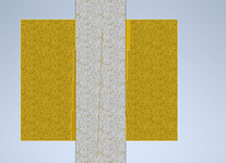
How do I properly measure and report the diameter? Is it as simple as the largest pin that will fit thru the assembly, regardless of tilt? Or, should the reported diameter be the largest pin that will fit while perpendicular to datum A (see picture of cross section below)?

I have an assembly made up four layers of different material laminated together, the resultant thru screw clearance holes are toleranced like this:

Datum A is the flat bottom of the plate (perp to the thru holes)
Datum B is a locating hole pep to A
Datum C is a slot aligned with B and perp to A
I have created a functional gage to check the 10 thru holes sized at 0.152" + (extra to account for gage stack up)
The four layers are often shifted relative to each other, resulting in a "tilted" thru hole
The assembly sometimes fails GO/NO-GO gage check at the small size
The assembly usually passes the functional gage check
Lets assume that the holes in the four layers are at the maximum size and the relative locations are assembly process limited
Questions:
If the part passes the functional gage check for the VC then does the diameter even matter?
How do I properly measure and report the diameter? Is it as simple as the largest pin that will fit thru the assembly, regardless of tilt? Or, should the reported diameter be the largest pin that will fit while perpendicular to datum A (see picture of cross section below)?

