Eng-Tips is the largest engineering community on the Internet

Intelligent Work Forums for Engineering Professionals

How to mesh spot weld

Status
Not open for further replies.

MatthewLynch

Mechanical
May 27, 2024
10
0
0
AR
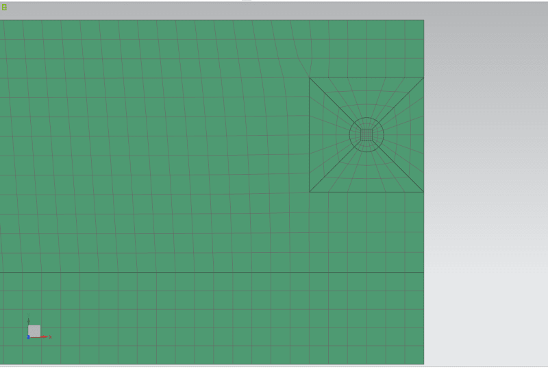
Hi, I am trying to mesh some spot welds in NX on a beam that is made of a C section beam with a steel plate welded on the top and bottom. This is how I am meshing at the moment, I am meshing it all with CQUAD4 elements and they are 5mm in size (not inside the spot weld).

Mallado_puntos_uyjbrc.png


When I run the Element Quality check they all get a warning. But I can't find how to get NX to tell me what is causing the warning.

Mallado_puntos_warning_slifov.png


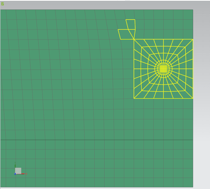
Is there a better aproach to meshing the spot weld? how can I know what causes the warning in the element quality to correct this?

Thank you
 
Replies continue below

Recommended for you

Why not just forget meshing the actual weld circle and just use connector elements between a uniform mesh to represent the weld joint stiffness and strength? Getting local stresses with a fine mesh in the weld area is basically useless.
 
SQComposites said:
Why not just forget meshing the actual weld circle and just use connector elements between a uniform mesh to represent the weld joint stiffness and strength? Getting local stresses with a fine mesh in the weld area is basically useless.

Sorry, I do not fully understand what you mean. Could you please elaborate a bit more?
 
Connection element: spring, beam, cbush, glue, etc - depends on the code you are using.

Presumably you have modeling the C channel and plates separately need to connect them.

Why exactly do you want to model the weld area in detail? And what results are you going to extract from the model in the weld area?

 
I have modeled the S channel and plates separately. What I want to get from the model is the load that each weld point is taking and the stress around the weld point.
What I do not understand of your comment is how can I represent a 9mm diameter weld point out of a uniform mesh. Maybe I am understanding you wrong, but what I understand from uniform mesh is that I do not do any other meshing besides the general square mesh I am using for the plate. And not the transition from this mesh to the circular weld point.

I am currently using RBE2 elements to connect the weld point diameter to a point on both the plate and the C channel. And later I use a CBAR element to connect the two points (one point on the C channel and one point on the plate).
 
Since you mention NX in your first post I suspect that you are using NX Nastran (Simcenter Nastran). There are weld-elements in that solver but I don't know if you can access them from the GUI you are using. There are several different methods in Femap but I would start with checking the manual.
 
The use of RBE2s to connect to the shell elements will give rubbish local stresses (because it is a rigid element).
Spot weld allowable strength should be in terms of shear and tensile force, not local stresses.
So the calculation of local stresses (even if one could accurately predict them, which is going to be very hard) is of no use. And to do it correctly you would need to somehow account for the varying material properties within the weld area.
So just connect a regular mesh with the CBAR elements, extract the CBAR forces and compare those to the allowable weld forces.
 
I'd just use a common node at the center of the spot weld ...

"Hoffen wir mal, dass alles gut geht !"
General Paulus, Nov 1942, outside Stalingrad after the launch of Operation Uranus.
 
Assuming this is a cover plate to the C-channel flange (increasing 2nd moment of area) or a connection of two C-channels, this is a good formula from your mechanics textbook:

H = Q*S / I

No need for any finite element analysis, and a linear one with shell elements will not give you useful results anyway, particularly not for a 9 mm spot weld.

The reason NX reports an element quality warning might be related to the fact that you have very small elements next to much larger elements, which causes ill-conditioning of the global system of equations. Very thin parts combined with very small elements can also cause shear locking.

PS. Spot welds are for applications where there are no significant internal forces. I would recommend you use either intermittent fillet welds, continuous fillet welds or butt welds when connecting a structural steel profile with a stiffener or strengthening plates.
 
Dear Matt,
For SPOT WELDS we are fortunate using Simcenter NASTRAN where we have the CWELD element, see my blog.
In FEMAP is ALL automatic using the CUSTOM TOOL APIs, simply define a TXT file with the spot welds XYZ locations and you are done.
In NX I suppose you have automatic methods as well. Forget at all to use complicated methods based in RBE2 & CBEAM elements, not need at all.
Although there are a number of different ways to model structural connections and fasteners in Simcenter Nastran, such as with CBUSH or CBAR/CBEAM elements or RBE2s, CWELDS are generally easy to generate, less error-prone, and always satisfy the condition of rigid body invariance.

cweld_definir_propiedades_fpaowe.png

01_cweld_kg4mob.png

02_cweld_usyfna.png


Best regards,
Blas.


~~~~~~~~~~~~~~~~~~~~~~
Blas Molero Hidalgo
Ingeniero Industrial
Director

IBERISA
48004 BILBAO (SPAIN)
WEB: Blog de FEMAP & NX Nastran:
 
Status
Not open for further replies.
Back
Top