Continue to Site

Eng-Tips is the largest engineering community on the Internet

Intelligent Work Forums for Engineering Professionals

  • Congratulations KootK on being selected by the Eng-Tips community for having the most helpful posts in the forums last week. Way to Go!

HOW TO MODEL THIS BEND

Status
Not open for further replies.

durablack2

Automotive
Jun 25, 2013
58
I need to model this bend (circled red in attachment) properly in Solidworks but am unable to figure out how to do so using the sheet metal tools. I don't really think it's possible to get what i need using basic extrude / cut tools either. Anyone want to take a stab at it or point me to some tutorials?? I can imagine the flat pattern but then the two tabs are somewhat twisted while bent which i am not able to achieve. It's a tricky one...

[link Your file's link is: ]Link[/url]

Thanks!
 
Replies continue below

Recommended for you

I would do it with base-Flange and Sketched-bend.
Or play with the Flex feature instead of Sketch-Bend (Insert>Feature>Flex), but that's be both overkill and unreliable for such a part.

S1_e34kie.jpg


S2_v2lhxq.jpg
 
When I have to make odd geometry through a bend, I make it with extra material, flatten, trim, and then rezbend.

Asymmetric ends on a bend like this cause trouble. The part is likely to shift in the die. Design it out if you can.
 
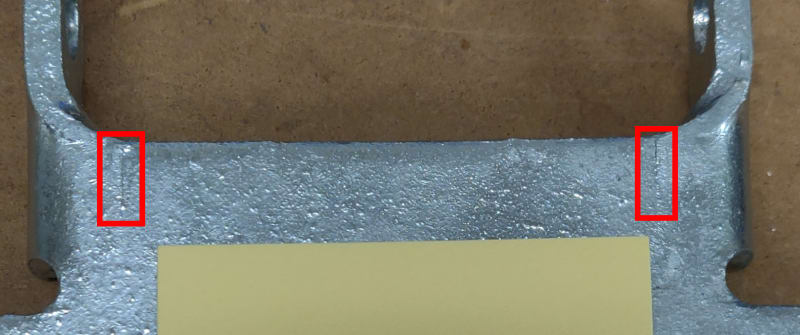
The object in the picture is a welded construction, not bent.
 
It looks like it had relief here and then was welded and ground flat. Other than those areas it looks like it is a true bend.

Welded_bend_zkde53.jpg


Scott Baugh, CSWP [pc2]
CAD Systems Manager
Evapar

"If it's not broke, Don't fix it!"
faq731-376
 
Looks to me like it's stamped in a progressive die. It's not purely sheet metal because the die does more forming than just bending.

 
Thanks for the responses everyone.

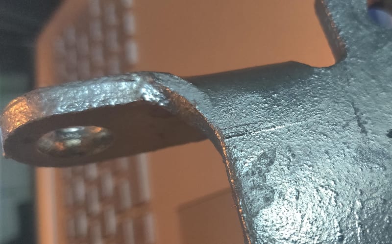
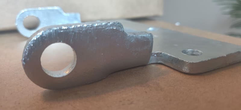
Sbaugh, it does look like it could be welded when looking at the pics I posted previously, but in hand it is clear those marks are tooling marks. This pic might be a little better.

part_1_2_ff4l8s.jpg


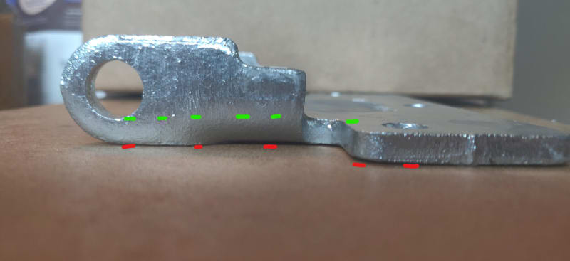
I think Handleman has it, the die is definitely doing more than just bending. The material is deformed a bit and twisted to get the geometry. The edge of the hole near the bend is tangent to the top surface of the flat plate (green dashed lines). The bottom of the tabs are collinear with the bottom of the plate (red dashed lines).

part_2_LI_voj0lb.jpg


part_3_ltseic.jpg


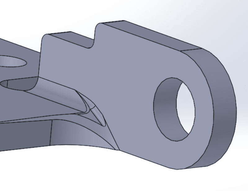
I think using the flex feature is the only way to truly get the geometry I need, but i think i can get close enough w/ sheet metal tools, some other features, and having a discussion w/ the supplier. I don't think I can work this geometry out of the design unfortunately.

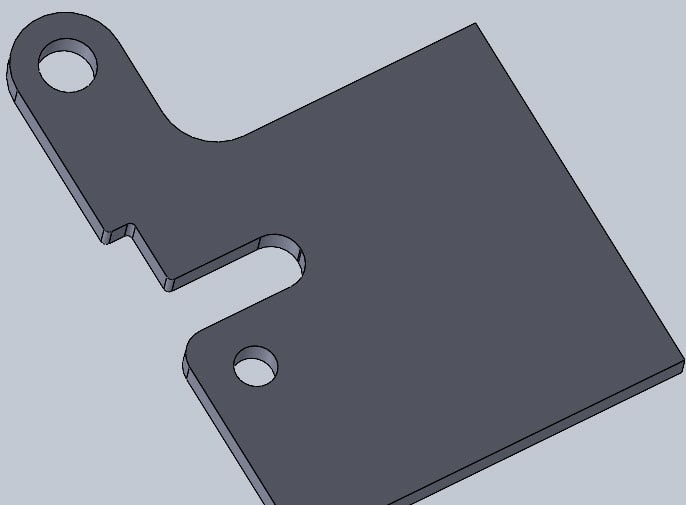
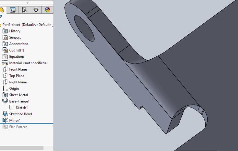
Here's a few pics of the model where it is now. Not perfect but I think it'll end up working.
[img [URL unfurl="true"]https://res.cloudinary.com/engineering-com/image/upload/v1587415651/tips/sw_pic_1_xvxvds.png[/URL]
sw_pic_2_erg21q.png
 
Status
Not open for further replies.

Part and Inventory Search

Sponsor