Continue to Site

Eng-Tips is the largest engineering community on the Internet

Intelligent Work Forums for Engineering Professionals

  • Congratulations IDS on being selected by the Eng-Tips community for having the most helpful posts in the forums last week. Way to Go!

How to model this problem? 1

Status
Not open for further replies.

thelostelite

Mechanical
Jul 30, 2013
5
Hello,
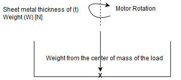
I’m doing a project of something like the trunnion mechanism which is a motor that rotates another motor, which is perpendicular to the axis of rotation of the first motor…
I need some insight about how to do the hand calculations for it, eg; what type of stresses should I check for? And the deflection as well? I need these to verify whether my modeling approach is correct or not.
For the main axis, I put a torque load on the holes that supports the motor mount, then added a fixed geometry on the bearing side… is that correct?

This is a photo of the whole concept:
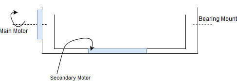
Whole_Assembly_dkeh27.jpg


I divided the mechanism into two main parts, Main axis of rotation and the secondary axis of rotation:
Main Axis:
Main_Axis_h11wth.jpg


Secondary Axis:
Secondary_Axis_liotrr.jpg


Replies continue below

Recommended for you

Could you add a pictures of the 3D model used for the analysis ? It would help us understand how this mechanism actually looks like. The general idea is clear but it's hard to get more details from these schematic drawings. If your FEA program allows for that (by the way - which software do you use ?), please attach a picture with boundary conditio symbols too.
 
Hello, @Fea Way, sorry for the late reply... strangely I didn't an email notification for your reply...
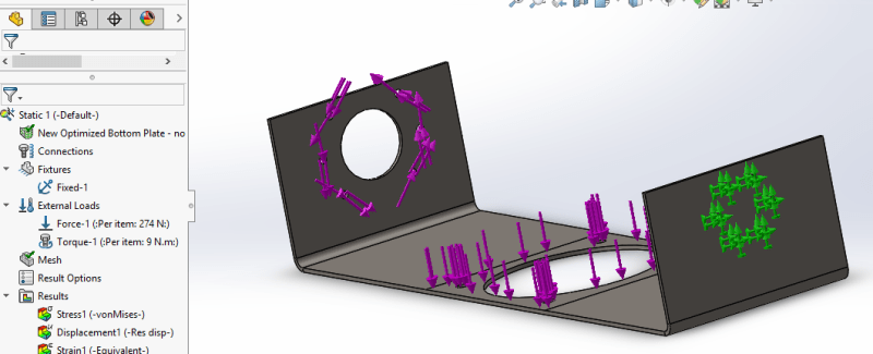
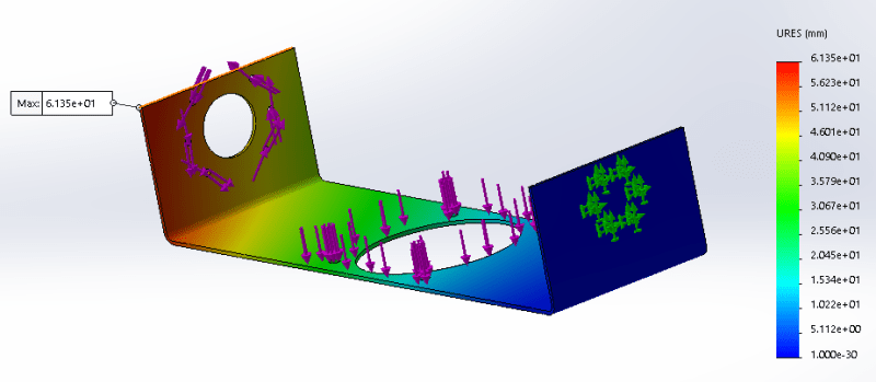
This is the main motor bottom plate, my main issue is here, in fact it gives me adequate stresses with very large displacements of about 6.2 mm !!! I thought that Solidworks switched to large displacement mode for plasticity problems, but it wasn't checked... that's weird..

I fixed the plate from the bearing side from the bolts, and added torque to the bolts holes on the side of the motor,9 N.m which is the maximum torque of the direct drive motor... also added the bending load of the secondary system..

Is my approach correct? or I'm missing something?
Main_Motor_Plate_iw64m5.png

Main_Motor_Plate_-_deflection_xdp2fr.png
 
Actually this is 61,35 mm (6,135 * 10^1). First of all check your material properties - especially Young’s modulus. There might be some error in units. You can also try modeling this with shell elements.
 
I'm imagining your "trunnion" is around 12-18 in. (30-45 cm) or so long, and made from something like 14 ga (.09 in., or about 2mm) thick steel...then the twist you are seeing in your model does not sound unreasonable. You could make your part stiffer in torsion if you close in the sides, or even just bend up/down some flanges along the long axis. Ideally, a fully tubular section (close all 4 sides of the rectangle) along that axis would give better torsional stiffness. Another thing - the thin area adjacent to the largest hole, presumably that is where a motor mounts? You might consider modeling the attached motor flange, as it adds stiffness to the assembly that is not accounted for in your model.
 
Yes I noticed I wrote it wrong, in fact it gave me larger deflection than that ! ( like 175 mm or something) which is insane !... it isn't about the material, it's about the boundary conditions I think, is it correct to model the torque like that way? also the bearing? because I modeled it as a fixed geometry, however when I modeled it as a pinned connection (No translations, just a rotation in one axis) it also gave me huge deformation (like 19.9 mm) which is obviously unacceptable.


@btrueblood : yea I also thought about the torsional stiffness, but with what you say that wouldn't be a truunion, I don't know what would it be but its function won't be any use for my case... I use 7075 Aluminum, 10mm thickness... I'll try modeling the motor flange, that's a great idea
 
Status
Not open for further replies.

Part and Inventory Search

Sponsor