Continue to Site

Eng-Tips is the largest engineering community on the Internet

Intelligent Work Forums for Engineering Professionals

  • Congratulations SSS148 on being selected by the Eng-Tips community for having the most helpful posts in the forums last week. Way to Go!

How to overcome lack of anchoring length in Reinforced Concrete Beams

Status
Not open for further replies.

kellez

Civil/Environmental
Nov 5, 2011
276
HI,

So i have a Reinforced Concrete Structure with beams, columns and slabs.
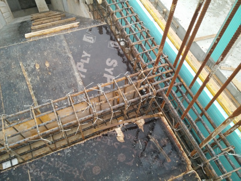
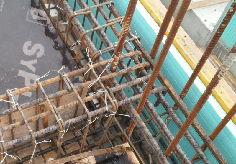
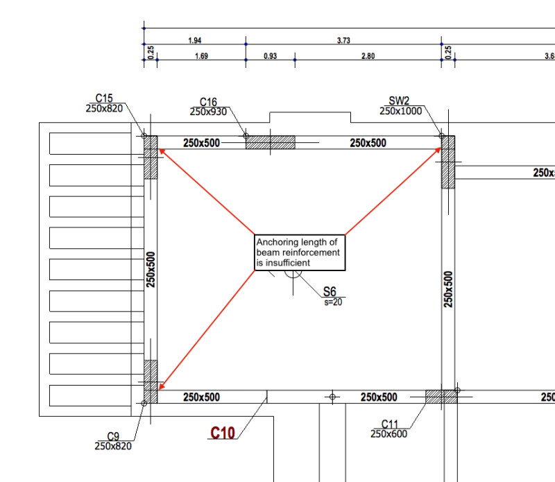
Columns and shear walls are 25cm thick, therefore you can understand that at locations such as edge beams there is lack of anchoring length for the RC beam reinforcement.
Please see picture for examples of edge beams with lack of anchoring.

Lack of anchoring results in the bars not being able to utilise their full bending resistance capacity.
Whereas the provided reinforcement is adequate for the bending moment in middle the bending resistance of the bars at the edges is considerable reduced due to lack of anchorage.

I have seen many houses being erected in the past year and none of the engineers used any kind of measure to increase anchorage resistance at edge beam locations.
Now that I am actually doing my first structural analysis and design for an RC Frame I have come across this issue and i am just wondering how did the other engineers overcome this?
or could they have not seen it or could they have just ignored it?


Screen_Shot_2017-09-07_at_17.36.29_pk4snh.png
 
Replies continue below

Recommended for you

Perhaps the beams were designed as pined at the joint and the top steel was just intended for crack control and overall integrity?

I like to debate structural engineering theory -- a lot. If I challenge you on something, know that I'm doing so because I respect your opinion enough to either change it or adopt it.
 
Ok, I am a young engineer therefore i may ask stupid questions but thats how i learn.

Here are my questions?

1. How do you actually decide if you can use a pinned or fixed support at a joint?
2. Is this depended on the actual construction of the structure?
3. For example; in this type of construction
a. The column is cast first at beam height,
b. Then the beams and slab are poured together on top of the column, therefore we have a monolithic element.
4. Since the columns, beams and slabs have not been poured all together does it mean that we can actually use a pinned support?

Please let me know if i am complete out of the subject.
 
Just bend the reinforcement down the column. I anchor all the top reinforcement at the beam ends to the inside of the columns, with a vertical code-compliant anchorage length (usually about 40 Diameters for S500 steel). The bottom reinforcement is just carried to the column face with a slight bent upwards. In seismic applications, if a positive moment is present, the bottom reinforcement is anchored too.
 
Hi,

In seismic conditions there is always a positive moment, it may not be of the same value as the negative though.

How do you actually insert the beam reinforcement inside the column since the column is cast in place first? This is one way to solve this issue but i have never seen it before.
Also this is not what they do actually do in practise here in my country, and they cant be all wrong.
 
Actually, no, there isn't always a positive moment for the seismic combination. It depends on the intensity of the seismic loads and on the magnitude of the vertical loads for the quasi-permanent load combination.

If the beam doesn't have sufficient height to do the rebar anchorage entirely inside its height, the beam top rebar (already properly bent) is placed alongside the column rebars (creating a top rebar lap at 1/3 span or similar). This is my standard detail.

If you look in the IStructE manual "Standard Method of Detailing Structural Concrete - 3rd Edition", they have another option which envolves the placement of U-bars after the column casting. It simplifies construction but I really don't use this detail for primary seismic elements as the column reinforcement is not fully mobilized and the anchorage doesn't seem to work as well.

Ultimately, it's your call, regardless of the practice of your typical contractors. I'm just trying to help you take an informed decision.
 
as avs... notes, I'd just bend them into the column or provide 180 hooks... I don't know how big c10 is, but, it appears that the spans are small and -ve moment shouldn't be an issue...

Dik
 
Just to be clear, the anchorage problem i have is only at seismic load combinations, ULS and SLS is fine.

avscorreia said:
Ultimately, it's your call, regardless of the practice of your typical contractors. I'm just trying to help you take an informed decision.

Thats the reason why i am here, I need advice on this. However its not the contractors choice how the bars are installed but the engineers. I suppose what i see on site its the engineers design.

avscorreia said:
Actually, no, there isn't always a positive moment for the seismic combination. It depends on the intensity of the seismic loads and on the magnitude of the vertical loads for the quasi-permanent load combination.

Well i think the intensity of the seismic load i use is pretty high, i am designing for a factor ag = 0.25g.
Also from the design response spectrum analysis to EC8, all of the beams get +ve and -ve moments at the supports.

avscorreia said:
If you look in the IStructE manual "Standard Method of Detailing Structural Concrete - 3rd Edition", they have another option which envolves the placement of U-bars after the column casting. It simplifies construction but I really don't use this detail for primary seismic elements as the column reinforcement is not fully mobilized and the anchorage doesn't seem to work as well.

I will check on that but i havent seen this before anywhere, I know its one solution but why dont they use it?


Please have a look at the picture below, this is one example of the anchorage used in my country.

Can someone discuss this anchorage example? Do you think this is sufficient for earthquake resistant structures?

20160107_163403_gymzxu.jpg


Screen_Shot_2017-09-07_at_20.11.42_iylqog.png
 
If this is a beam on the wall/column on the photo above, id consider beam as pinned at supports since you dont have sufficient anchor lenght from upper zone of the beam to supports (wall/column). In reality its not totaly fixed nor pinned but something in between, but for analysis id use pinned. I often use both models if Im not sure what to consider and choose reinforcing based on both models. But im not that experienced myself so you should listen what others have to say.
 
Thank you everyone for your replies.

Some of you have suggested using pinned supports, therefore my question now is:

In reality, in an RC frame where the beams and slab are poured together on top of the already cast column The beam-column joints are:

1. pinned
2. fully fixed
3. something inbetween
4. Depends on how you carry out the analysis & design (if you use more steel reinforcement in the joint then the joint will be able to resist a bigger moment),
similar to the steel frame joints, where you actually choose what connection to use.


Are there any articles to read on these? maybe some experiments?
 
THIS:

3. something inbetween
4. Depends on how you carry out the design, similar to the steel frame joints, where you actually choose what connection to use.

when you make a model you have to choose one idealized extrem: pinned or fixed. For some advanced models you may use a spring like support with a stifness that is something between fixed/pinned but you have to know what you are doing. I dont do that...

in real world its rarely one extrem or another. But based on how you will detail connections / reinforcement details it will act more towards one extrem than another.
 
Ok now I totally get it, You couldnt have explained this any better, thanks a lot for your time, so many years in University,
so many hours of studying and i still didnt know this, noone explained this clearly.

i knew that the RC beam-column connections are neither pinned neither fixed, however I totally missed out on the fact that
the behaviour of the connection can be adjusted through the reinforcement, similar to the steel frame connections.


I have one more question for you mats12, when designing an RC frame house (2 storeys) do you usually use both fixed and pinned
beam-column joints around your model? and how do you decide on the pattern so that you have a stable frame?
 
For base of columns I use fixed supports (if you have a completely new structure. If you are doing an adaptation/reconstruction of existing building and you have to anchor new columns to existing concrete, then I use pinned supports at the base since its hard to achieve fixity by epoxing new rebars to existing concrete) but when supports are fixed - from a moment at the base I calculate rebar anchors (which are sufficiently anchored to new foundation). All other connections between columns - beams I consider fixed - I detail reinforcement in joints accordingly. Sometimes (it depends on structure - how many storeys, dimensions of columns, beams) I control forces in beams - column by making another model with pinned supports (that way you ll get much bigger moments at column - beam connection).


If you want your frame to be horizontaly stable (in both direction) you either have to have:
-fixed base + fixed or pinned connection between columns - beams (you have to reinforce joints/connections accordingly)
-fixed base + pinned connection between columns - beams (large moments at the base of columns - I wouldnt do that for structures with more than one storey)
- you have pinned base but in this case you have to have fixed connection between columns - beams.
 
Ok that makes sense, so in my case what do you suggest?

I have an issue with insufficient anchorage length at almost all corner/edge beams due to very low thickness of columns/walls (25cm)
and due to the high seismic forces.

How can i decrease the moments at beam-column joints for these beams so that i do not need so much anchorage?
 

Are you dealing with a project that is half way done (photos you posted) and now you are concerned about details or are you asking for structure that hasnt been designed yet?
 
I am asking for a structure that hasnt been designed yet, the picture of the beam reinforcement is just to show the type of anchorage used in the most recent projects i have seen, and most of them are using this type of anchorage. They dont seem to use enough anchorage thats why I am a bit confused. And when i started to do my first design I have a problem with insufficient anchorage at corner/edge beams and i was wondering how come the projects i have seen dont use that much anchorage? How to they overcome this?

I think i have two options here:

1. Use a fixed beam-column joint and Find a way to increase the reinforcement at the joint in order to provide more anchorage.

or

2. Find a way to decrease the moment at the beam-column joint so that less anchorage is required.
 
Even if you consider pinned joints in your analysis, Eurocode 2 defines in clause 9.2.1.2(1) for monolithic construction that a minimum bending moment must be considered in design at the support section. You need to anchor the reinforcement needed for this nominal moment and the pictures you have shown are not the proper way to do it, since there isn't sufficient anchorage length.
 
EC2 9.2.1.2(1)States that even when using pinned supports, the supports should be designed for a bending moment arising from partial fixity of at least 􏰁b1 of the maximum bending moment in the span. whereas b1 = 0.15.
I will have to check and see how much the bending moment decreases at the supports when using 0.15(MEd at span) compared to the bending moment at the supports with a fixed support.
 
Can someone correct me if I am wrong, but if you provide a percentage of steel over what is required then your development length can be reduced by that amount (ACI code). Would this be satisfactory to consider this condition fixed?
 
Status
Not open for further replies.

Part and Inventory Search

Sponsor