Continue to Site

Eng-Tips is the largest engineering community on the Internet

Intelligent Work Forums for Engineering Professionals

  • Congratulations IDS on being selected by the Eng-Tips community for having the most helpful posts in the forums last week. Way to Go!

How to PIN a 3D rigid body? 2

Status
Not open for further replies.

JDSOMO

Bioengineer
May 11, 2021
6
Hi all! Let's say I have some 3D rigid body that I want to "pin" through some arbitrary axis, such that the entire body rotates about this axis. Here is a sketch that may help:
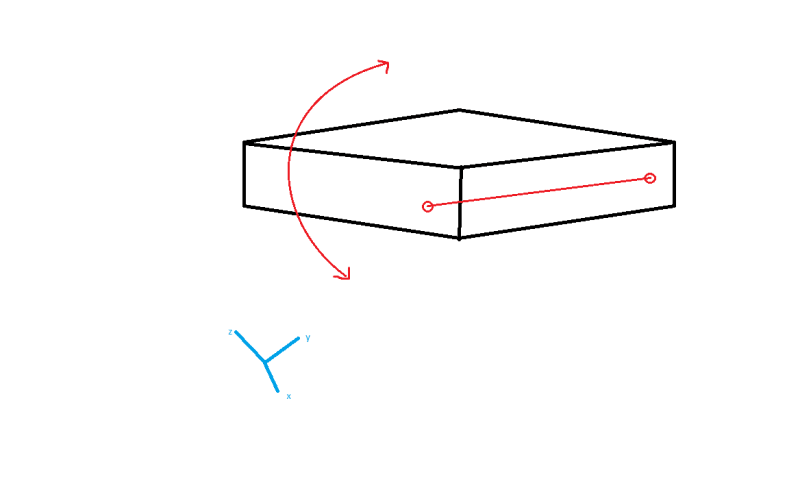
sketch_rigid_motion_vojp4o.png


Any idea how I can do this? seems simple enough but playing around with MPC and rigid body constraints led me nowhere. I am open to either Abaqus/Standard or Explicit. Thanks a lot!!!
 
Replies continue below

Recommended for you

You can try using hinge connector for this purpose. It provides a revolute constraint between rotational degrees of freedom of two nodes and is meant for similar puproses.
 
Thanks for the quick reply - so do you mean (1) create a wire feature between the two points on my rigid body, i.e., connect two nodes that are part of my discrete rigid mesh, and (2) define a hinge connector on this wire? I will give it a go and report back.
 
Since the body is rigid, you should attach the wire to its reference point.
 
This is a rigid body and you want a free rotation about this axis?
Just place the reference node on the axis, create a coordinate system aligned with the axis and use it to apply BC at the ref node.
 
@Mustaine3 - I did try that, but the problem is that I cannot JUST have UR1 free AND have a local CS. For some reason, when I try setting a "Displacement/Rotation" BC in either the initial or subsequent steps, I cannot change from the global CS.
 
In the Edit Boundary Condition window for Displacement/Rotation type there’s a CSYS selection tool. By default it’s set to Global but you can click the button with arrow symbol to edit CSYS. Next to it there’s also a button with coordinate system symbol that can be used to create datum CSYS.
 
Yes I know, but the selection is only possible if I use "Symmetry/Antisymmetry/Encastre", and here I can select 1 BC which is XSYMM (U1 = UR2 = UR3); so now I just need to fix U2 and U3, but this is not possible because if I create another BC with "pinned" for example (U1=U2=U3), then it complains about double BCs on U1. Hopefully that's a bit clearer.

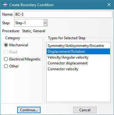
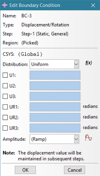
Additionally, if I try to apply a rotational BC to the RP; I cannot change the CSYS:
a_mvc9f4.png
b_mtmwmz.png
 
Most likely this BC was created in a different step, you can change CSYS only in the original step (in this case it should be Initial).
 
I tried all sorts of combinations with displacement/rotation but it didn't seem to work (also defining the BC in Step-1); however, what seems to work, i.e., allow me to select the local CSYS, is to use the "velocity/angular velocity" boundary condition. Not too sure why? But at least it's producing the desired results. Now to increase model complexity! So I will probably be back with more questions... Thanks for all your help.
 
Which version of Abaqus do you use ? If you already applied some displacement BCs in global CSYS to this point then Abaqus/CAE may block you from applying BC in local CSYS for the same point.
 
I am using 6.14-1. FYI: I just tried that to be sure: deleted all BCs at the reference point & apply a BC in step-1 (not initial) - if I use displacement I cannot change from the global CSYS, but when I use velocity, I can change it.
 
It might be some limitation or bug in this quite old version. In current release (2021) there’s no such issue.
 
Status
Not open for further replies.

Part and Inventory Search

Sponsor