Continue to Site

Eng-Tips is the largest engineering community on the Internet

Intelligent Work Forums for Engineering Professionals

  • Congratulations KootK on being selected by the Eng-Tips community for having the most helpful posts in the forums last week. Way to Go!

How to prevent metal dust in the dust collectors system from malfunctioning the level sensors? 1

Status
Not open for further replies.

Imposter666

Mechanical
Jan 15, 2021
36
Hi,
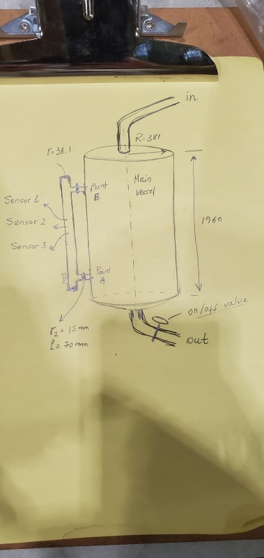
Please see the attached image. We have this dust collector system that sucks metal dust from grinder(0.05mm-0.1mm)which gets mixed with water and gets kicked out from the bottom of the main vessel. When pump gets activated there is quite a turbulent flow inside the main vessel. On the side tube, we have 3 sensors for detecting high, low water levels and a float switch in the middle. These sensors don't last long in this hostile environment. I am thinking to put some sort of filter at Point A and Point B to prevent metal dust to pass to this side. However, it is important that water has free/uninterrupted movement with no lag here. Unfortunately the manufacturer doesn't have a countermeasure in place. Our application seems to be more "dirty" compared to what others use this system for. Is placing a filter at point A and B a good idea? If not, what can be done to prevent down time related to sensor malfunction? If filter idea is good, what type filter needs to be used here?
Thank you!
20210623_091722_zthlw9.jpg
 
Replies continue below

Recommended for you

The float switches "hang up" due to the dirty conditions?

I'm not sure what 381 or 1960 are; inches, mm, cm?

First alternative technology that comes to mind is a conductivity switch that uses a full length reference rod and a rod cut to the length at which the switch point occurs. The rod assembly mounts from the top. When the conductive water reaches the bottom of a level rod, an electrical current passes between the level rod and the reference rod. An electronic box connected to the rod assembly trips a relay as an output signal. Depending on dimensions, the rod assembly might mounted in the top of the bypass pipe. As long as the wet dust doesn't bridge between any level rod and a reference rod, it'll work.

2nd alternative is vibrating 'fork' point level switches. The fork on the end of the probe mounts at the trip level. When water covers teh fork its vibration rate changes and trips the electronic circuit. From memory the gap in the fork is about 12mm or 1/2". If the fork is bridged, then one gets a false ON signal.

3rd alternative is a capacitance point level sensor, which can be mounted horizontally or vertically. The Siemens CLS100 tips are teflon and pretty slippery. However, if residual dust settles out and coats the teflon sensor tip it could give a false reading.

4th alternative is an ultrasonic non-contact sensor mounted on the top of the vessel. Any ultrasonic level device will bounce its signal off water (they're now 5th generation devices), but the ultrasonic cannot be against the wall of the vessel (the radiated beam is cone shaped) and the beam will not shoot through an inflow of material from the top. So mounting an ultrasonic level sensor is dimensional dependent on the tank. Same conditions apply to top mounted non-contact radar. Ultrasonic/radar is a continuous level signal, so you'd need a panel meter with alarms to trip at the low/medium/high points (typically the panel meter supplies the 24Vdc loop power to the ultrasonic.

5th alternative is a bubbler - run compressed air through a differential relay (constant flow regulator) at a flow rate of about 1.0 SCFH, run the regulated air to a 3/8" OD tube run vertically down the vessel. Tee a low level pressure sensor (gauge or transmitter) into regulated air line and the pressure will be the elevation of the liquid above the bottom of the tube. Will work as long as the regulator does not gum up from oil and water in the air. A coalescing filter on the inlet helps remove some of crap in the air.

A bypass indicator uses a float so it is not likely to work any better than your float switches.
The optical point level switches are likely to suffer residue on the lens that affects their operation.
Top mount Infrared continuous is expensive and not widespread, although the IR beam is much narrower than radar or ultrasonic, making installation less problematic.

 
I think the only viable option missing from danw2's good and comprehensive post ist a pressure sensor mounted in the bottom (or a differential pressure sensor if the air pressure situation above the water level is very complicated).

You could mount a fatter pipe (if the diameter is 38mm it's one nominal size to small :( ) to the side so a rod sensor fits, then attach pipe coupling so you can flush the sensor with fresh water if any bridging occurs.
 
Do you know the failure mode of the pressure sensors?? Are they plugging up or completely failing? If this is a open tank, meaning its not pressurized and is open to atmosphere, you could use a pressure/ level sensor threaded it into the side of that tube (Down near Point A) and it will give you the level inside that tube plus the tank level above point B. Using a 4-20mA level/ pressure transmitter possibly tied to a simple panel meter with relays you can calibrate this to give you a continuous level reading and with relays turn the pump on and off. It would be great of you knew the failure mode of the sensors though. You could possibly mount a level sensor to the bottom of the tank itself and measure the full head pressure but if there is a lot of turbulence it can cause the reading to jump around unless you filter that, like thru a the panel meter.
 
Is the metal dust magnetic? Can you install a magnet to remove the metal from the water?
 
Status
Not open for further replies.

Part and Inventory Search

Sponsor