Continue to Site

Eng-Tips is the largest engineering community on the Internet

Intelligent Work Forums for Engineering Professionals

  • Congratulations KootK on being selected by the Eng-Tips community for having the most helpful posts in the forums last week. Way to Go!

How to properly send out a structural member drawing to machinist? 1

Status
Not open for further replies.

Space213

Mechanical
Oct 27, 2017
81
hi guys, I have a structural C channel rectangular base with 2 strips of angle iron going through the middle of the C channel base. Then I have a 1" square tubing that is placed on top of the Angle iron. I want to send this out to a machinist so I can get it built but not sure how to go about the Shop/machine drawings so they have the proper dimensions laid out.

Ill be sending my machinist the 3D cad model of the base and will start to work on the shop drawings for the base as well but I am getting different responses on how detailed I need to be with the shop drawings.

Here is an attached picture below of what the base looks like. How would you go about giving the proper dimensions for this when sending it to a machinist to build? All are standard metal parts.
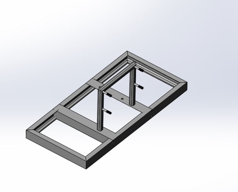
base_yfooih.jpg
 
Replies continue below

Recommended for you

Is the machinist supposed to mill the welds on a latbe?
 
I don't think you can have steel inside of steel?

You are going to have to clean this up or no one is going to make it.
Weldments_cscsut.jpg


I would flip the outside frame around and use the flat side of the steel to work with. Coping the cross members to fit the inside of the is going to suck and be expensive. Attached is a frame I made for one of our generator bases late last year.

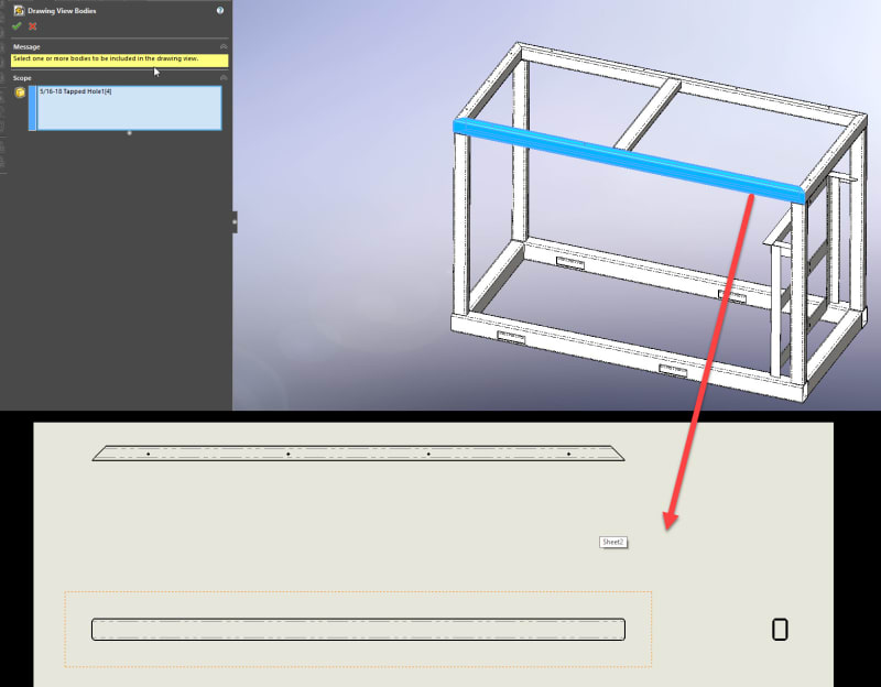
If you made this as a weldment part you can make the first sheet your weldment cutlist and the location\welding symbols sheet. Then on the next sheet, you select which bodies you want to see and make a drawing of all the individual bodies and include them all in one drawing.

For Example:
Body_to_drawing_view_ajscrc.jpg


I hope this helps,


Scott Baugh, CSWP [pc2]
CAD Systems Manager
Evapar

"If it's not broke, Don't fix it!"
faq731-376
 
Also, I have found its less expensive usually to just use steel and have it bent than to use structural steel. The reason is you pay for an entire stick, then they charge you a drop charge. You don't get the whole stick you bought. You only get what is in your design + the drop fee. Its like they are getting paid twice on structural steel. However depending on the size of your angle\tube maybe its less than it is to have a piece of steel cut and bent.

You have to contact your fabricator and ask. Our fabricator told this to me directly, so I rarely use steel structure.

Scott Baugh, CSWP [pc2]
CAD Systems Manager
Evapar

"If it's not broke, Don't fix it!"
faq731-376
 
Our frame welding guy recommended to me to use square or rectangular tubing if possible rather than angle or channel. It comes in much nicer, straighter, and easier to work with. The material itself is a little more expensive, but you save labor by not having to cope joints or work with warped material.

Our internal shop always had our commonly used sizes in stock, so we didn't worry about drop charges or whatnot.

Your frame is simple enough that a competent shop should be able to weld it up from three views, outside dimensions, and material size notes. Probably no need to go detailing every cut piece with its own views.
 
If you are doing it in-house then yes your right handleman drop charge is not an issue. We farm everything out so its big deal to us.

As for the tubes being straighter, that's only true when you're using shorter lengths. the longer the tube the more twist and wrappage you see.

Scott Baugh, CSWP [pc2]
CAD Systems Manager
Evapar

"If it's not broke, Don't fix it!"
faq731-376
 
thanks for the responses guys.

Sbaugh,

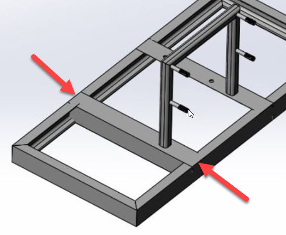
The dimensions of the bottom base is 32" by 15". The angle iron that is going into the C channel where you mentioned it should be cleaned up I am not sure if I should actually the the angle iron at the end to the exact spec profile of the C channel is? I use solid works and wasn't sure how to actually clean that part up.
 
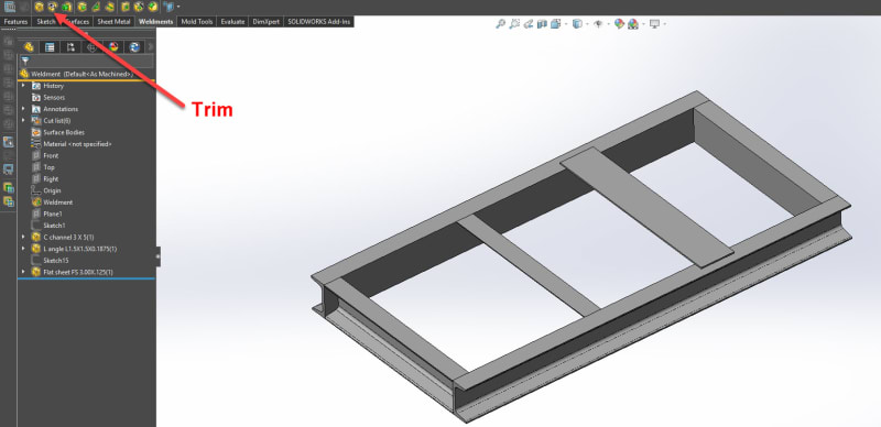
I would not make your frame like that, whether you did it in SW as a weldment or not. If you did not make it as a weldment you're going to have to convert the edge from the other component (plus welding gap) to trim it. If you did make it as a weldment you can use the trim tool.

Attached is how I would make your design and it looks a lot cleaner and it's easier to build, plus it's FAR less expensive. If you want to waste money I will be happy to take some off your hands.[roll1]

Honestly, I probably wouldn't even use C channel because it's just too expensive anyway. A piece of u bent steel would be sufficient. Varying on how much weight you plan on putting on it would vary the thickness. Everything I make here is usually .1875 to .250 thick because I have over 1500+lbs pushing down on it. I would venture to say I could go a little less thick, but when in doubt make it thicker [flip].

Weldment_Base_fahope.jpg


The attached file is in 2018.

Scott Baugh, CSWP [pc2]
CAD Systems Manager
Evapar

"If it's not broke, Don't fix it!"
faq731-376
 
i cleaned it up. now i am just finalizing the dimensions and making sure its all clear on the shop drawings for machinist.

thank you!
 
I might have to try and do Bent U channel instead then. Thank you for telling me
 
when you want to weld angle iron into a C channel would a butt weld be the proper type of weld for that? what type of weld would work best?
 
Space213
Would love to see some pics of your drawings when you're done.
Sounds like you are a serious newbie thrown in head first.

David
Connect with me on LinkedIn. Quote: "If it ain't broke, I must not've fixed it good enough"
 
Status
Not open for further replies.

Part and Inventory Search

Sponsor