RichardStarrbuck
Mechanical
Good morning all,
I am trying to figure out the best way to show a pipe coping detail in a drawing using AutoDesk Inventor.
I have a length of aluminum tubing that needs coping at both ends. Some of the coping is 90 degree some are different angles.
Is it typical to just give a diameter and an angle for the coping?
Do you put this information in a note or show it in a detail view?
Any help would be appreciated, please show examples if possible, thanks.
I am working on an example at the moment and will show my work here when done. I figured in the meantime I would ask for a little guidance on the subject.
EDIT:
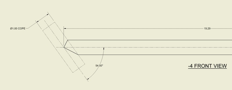
Here's what I came up with for one end of the tubing. I still need to show coping at the other end but it will be cut perpendicular to the face shown here. I would really like to come up with an isometric view for this, I think it would look better and show a better representation for what we want our part to look like.
Again, any advice on this would be appreciated.

