Continue to Site

Eng-Tips is the largest engineering community on the Internet

Intelligent Work Forums for Engineering Professionals

  • Congratulations KootK on being selected by the Eng-Tips community for having the most helpful posts in the forums last week. Way to Go!

How to Reduce 3 Phase Voltage 3

Status
Not open for further replies.

gary10

Automotive
Feb 8, 2002
13
I need to run some tests on my mechanical system which is powered by the star connected 208VAC 400Hz motor that I asked about in an earlier thread (thanks for help). As I don't have access to 400Hz power for these tests I would like to run the motor on 60Hz 3Phase. According to the FAQs, I should use about 30VAC on each leg.

Is there an easy way to reduce 220VAC 3Ph to 30VAC 3PH? As the real load will not be present, I don't need full speed or power from the motor for these tests. Or, is there a way to obtain 400Hz by using a modified alternator? Either way would be acceptable.
 
Replies continue below

Recommended for you

One consideration will be the performance of the DC link capacitors at 400Hz. Their ripple current rating will be different to that at 50/60Hz. Gut feeling is that they would be fine, but in these days where so much is manufactured to barely perform to nameplate specification it would be worth checking.

Standard rectifier diodes should be fine at 400Hz. If this was a very large drive I would be more concerned with the rectifier's behaviour because very large semiconductors are s-l-o-w, but not at the kind of power rating you would supply at 208V. Avoid using a drive with an active (power factor corrected) front end. The controller IC used in PF-corrected drives might be capable of operating at 400Hz but probably not without component changes.

----------------------------------
image.php
Sometimes I only open my mouth to swap feet...
 
itsmoked said:
Cross post?
Where? Do you mean he should have started a new thread? He's the OP, he appended his own post. Is that considered cross posting? Not being critical, I'm just wondering if this is some netiquette that I was heretofore unaware of.

 
ScottyUK,
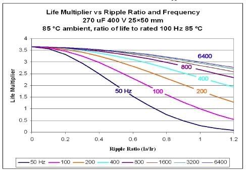
As I learned it, the Ripple Current rating in a capacitor is based on the power generated in it (heat loss), calculated
P[sub]gen[/sub] = I[sub]rms[/sub][sup]2[/sup] x ESR where:
[tab]P[sub]gen[/sub] is the Power generated
[tab]I[sub]rms[/sub] is the magnitude of the current ripple, and
[tab]ESR is the Equivalent Series Resistance of the cap.

ESR goes down as frequency increases and ripple rms current goes down as frequency increases into a bridge rectifier, so essentially if a capacitor is designed for a lower frequency it will work fine at a higher one. The problem as I see it would be using a cap designed for a 400Hz application in a 50/60Hz supply. There are lots of other factors, but this image sums it up nicely.
Capacitorlife.jpg

Image taken from this paper: "Deriving Life Multipliers for Electrolytic Capacitors: A Brief Explanation" which can be downloaded in .pdf from the following website (direct link to paper is disabled).
http:/Eng-Tips: Help for your job, not for your homework Read faq731-376 [pirate]
 
jraef,

Good link - thanks for the reminder. Looks like gut feeling was right!


----------------------------------
image.php
Sometimes I only open my mouth to swap feet...
 
This should be the final note on the subject. I have been running the VFD unit on 400 Hz for about 10 hrs. There haven't been any problems. I'm able to let my spare unit remain powered up at the high frequency so I'm just going to keep track of the hours at 400 Hz.

The data that was posted from Cornell-Dubilier indicated to me that I probably wasn't going to see any problems.

Thanks again to all who replied.

Gary Knutson
GLK Design
 
Status
Not open for further replies.

Part and Inventory Search

Sponsor