Continue to Site

Eng-Tips is the largest engineering community on the Internet

Intelligent Work Forums for Engineering Professionals

  • Congratulations cowski on being selected by the Eng-Tips community for having the most helpful posts in the forums last week. Way to Go!

How to reduce torsion on the beam? 3

Status
Not open for further replies.

Blackstar123

Civil/Environmental
May 5, 2013
253
I've a structure supporting a steel silo.
image_chdrws.png


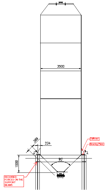
I've calculated forces on the supporting beam assuming the load path as shown in attached Figures.
image_scen5y.png


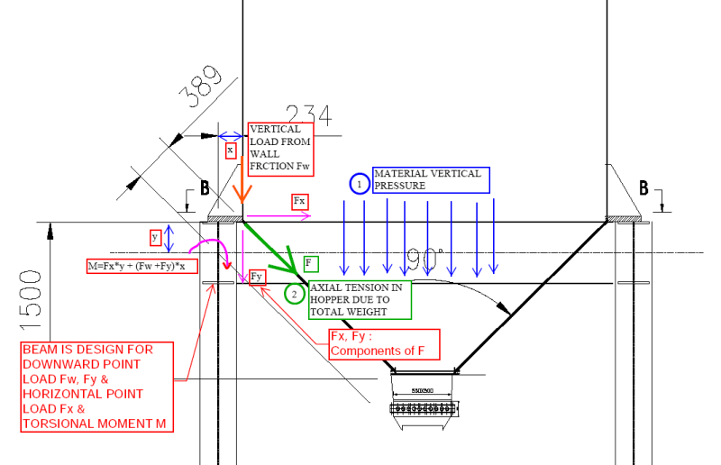
I'm trying to pass the supporting beams in torsion, which is coming out to be quite large due to heavy load (Tu = 130 KN-m = 1145 kip-in). There's a maximum limit beyond which I cannot increase the beam width further. This left me to play with the depth of beam and thicknesses only. Increasing depth is inadvertently increasing the eccentric moment due to horizontal force.

I'am thinking it's better to look at options to reduce the torsion first than keep on trying different beam sizes.

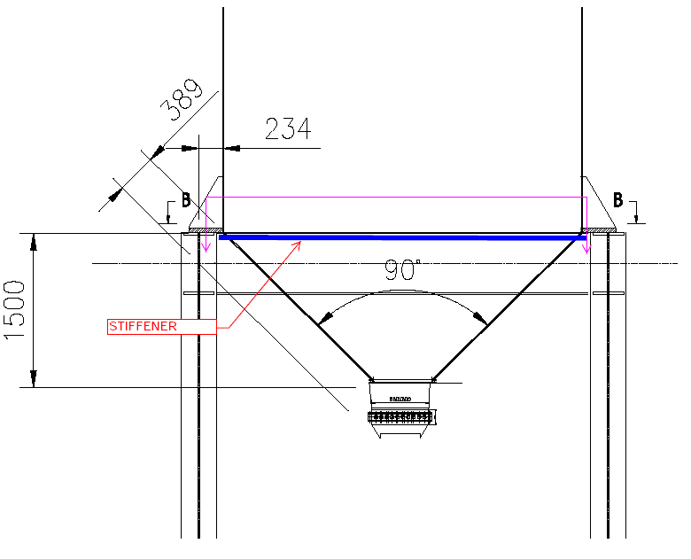
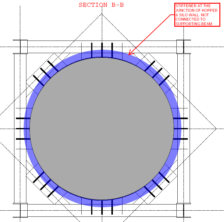
Question is, If a stiffener is provided at the junction of silo wall and hopper as shown in the figure below (which is not connected to supporting beam) then am I right in presuming that the horizontal force will not be transferred to the beam and it will be in equilibrium due to axial force in the stiffener?
image_nopilp.png


image_x98zm8.png


P.S. I am not responsible for the design of steel silo. It is in the scope of others.
 
Replies continue below

Recommended for you

Is the silo designed to take the moment from the supporting lug? If so, I would look at the lug being supported at the web of the supporting beam and no torsion. Any rotation would put the load on the web and would actually place the load on the opposite side of the web centreline.

Dik
 
The designers of the silo and support system have to agree on how the eccentric moment is to be handled. Clearly, the silo shell can't resist that moment on its own.

BA
 
[blue](Blackstar123)[/blue]

Could you please explain this with a sketch?

............
Just so you know.. I'm a she, not a he..

Sorry for the wrong guess on gender and a pic is attached. Obviously it omits other framing (for clarity). (Including a number of stiffeners that would be needed on the beam where the torque was applied.)

I've used this a few times when the torques get high (in the 100-300 ft-k range).

EDIT: This detail is also useful as far as rotational/P-Delta control goes. One thing about relying on the rotational stiffness of a beam for stability.....it becomes a problem. Once the silo starts coming over....it doesn't want to stop based on the rotational stiffness of most beams.

[blue](Blackstar123)[/blue]
Since silo design is not shared with us, I can't comment on this with surity. But I've sent an email to client, requesting them to share the design of steel silo with us.

I'd definitely clarify the situation with them. From experience, I'd say it is unlikely they are counting on your framing to keep the thing together. The bear in these things is when you get a high silo and the uplift forces get big (from lateral). (Good reason to put them on concrete where possible.)
 
 https://files.engineering.com/getfile.aspx?folder=bc9ccb94-a0bd-430d-b1f7-c1babdb598e8&file=7.25.20_001.jpg
Blackstar123 said:
I've desined RCC silos with hopper resting on a ring beam in the past. The ring beam was designed for similar forces as shown in my original sketch.
Which would probably make you one of the most knowledgeable people here regarding the forces of bulk materials on the silos walls. So I would hope that most of these answers are telling you what you already know.

But it does sound like you are being too clever for your own good. You seem to be assuming that you as the structure designer need to design for unresolved internal silo loads. The rest of us are assuming the silo is a complete structural unit as it is a externally supplied item.

It would be very odd for a supplied silo to need additional ring support. But this should be resolved with your supplier.

For larger hopper silos I am used to seeing very explicit compression rings. Eg something like this:
silo-tolva-metalica-estructura-inferior-symaga_vs0wtw.jpg


BAretired said:
The designers of the silo and support system have to agree on how the eccentric moment is to be handled. Clearly, the silo shell can't resist that moment on its own.
This is pretty crucial. But I would presume if the lugs provided by the supplier then they have that covered. That said, I'd like to see what they've done here because that is a pretty big eccentricity for a heavy load.


Blackstar123, do you mind revealing your supplier to us? Is it one of their standard designs?
 
Industry silo usually has varying thickness from top down, can get quite thick at support level due to buckling concerns. Also, for extreme high demand, it can be locally strengthened with plate, or a ring of plates. WARose' idea is sound. Invert Tee has also been used to stiffen the hopper.
 
Blackstar123 (Civil/Environmental) said:
You're right I am not, but what if silo is design such that the force is transferred to supports as I showed. I am responsible to provide the client with possible solution for efficient design

Dear Blackstar123, i screened the responds of fellow engineers. To my best knowledge , there is no a dedicated standard, showing rules, recommendations and examples for the steel elevated silos and tanks.

IMHO, the silo supplier shall design the transition junctions and supporting ring and provide the loads with different loading combinations for designing the supporting structure.

If this is not the case, and the if the silo will be supported with eccentric lugs, the moment developing should be resisted with two continuous compression and tension ring stiffeners welded on silo shell.
IMO, the use of concentric supporting columns beneath the shell or R.C. frame with thick supporting slab could be considered.

The below picture is taken from (Eurocode 3 - Design of steel structures - Part 4-1 Silos)

ring_forms_q34drx.png


The below picture is taken from (PRESSURE VESSEL DESIGN MANUAL 4.Ed.Dennis R. Moss)
moss_1_pizmhn.png
 
BaRetired said:
How about moving the supports inward to avoid eccentricity?]
Can't do this. As per the drawings, supplier wants the supporting beam at hopper wall joint. Moving the center of beam exactly under the wall center line will require me to either move the supporting beams down or lift the silo up.

human said:
1. I presume this is an outloading structure used for vehicle filling?
2. I don't see an issue with torsion unless the silo is poorly designed and the supporting lugs are not stiff enough and allow rotation (eg due to the eccentricity of the lugs and load) But I would feel pretty safe in assuming they are because that is what they are there for.
3. do you mind revealing your supplier to us? Is it one of their standard designs?
1. No, not vehicle filling. It's feeding material to a belt conveyor.
2. I agree with this. A very stiff ring around the silo will be very hard to displace laterally and will not produce a significant horizontal reaction at supports. Which, I can't tell is the situation from the drawings I have. But as you and others have pointed out several times that, a silo designer would have most probably designed the silo for such forces already.
3. Client has not shared this information yet and I can't tell from the given layout drawings which only have the client's stamp. I think it's their inhouse design because the project was originally supposed to be a vetting job which converted into design job once it became clear that designed has not designed the structure for lateral loads.

WARose said:
I'd definitely clarify the situation with them. From experience, I'd say it is unlikely they are counting on your framing to keep the thing together. The bear in these things is when you get a high silo and the uplift forces get big (from lateral). (Good reason to put them on concrete where possible.)]
Still waiting for their response. And, thank you for clarifying your suggestion with the help of a sketch.

HTURKAK said:
To my best knowledge , there is no a dedicated standard, showing rules, recommendations and examples for the steel elevated silos and tanks
I've been searching the internet and office library for a design example since morning. The only example I could find is in an old book by a author named Reynolds for a steel silo supported on a RCC ring beam. The forces on column are determined by taking into account the stiffness of the ring beam. I am attaching the relevant snapshots.
image_gltjn2.png


image_gkxatn.png


image_udvr5b.png
 
Status
Not open for further replies.

Part and Inventory Search

Sponsor