Eng-Tips is the largest engineering community on the Internet

Intelligent Work Forums for Engineering Professionals

  • Congratulations waross on being selected by the Tek-Tips community for having the most helpful posts in the forums last week. Way to Go!

How to reinforce an existing reinforced concrete slab due to a creation of a future opening 1

Status
Not open for further replies.

Structural-eng.

Structural
Oct 9, 2020
9
0
0
CA
Hello all. I am currently working on a project whereby we are required to evaluate and potentially reinforce an existing concrete slab due to the creation of a future 4 feet by 4 feet future opening for electrical conduits. We are dealing with a very old building that is in good shape (built in 1930). The challenge here, is that the rebar has been placed both orthogonally and diagonally (I am not sure what the reason is, we do not have any existing calculations). The future opening would therefore cut through what seems to be the main bottom bars. Can anyone please provide consultation on what should be done to reinforce the slab, and confirm that the diagonal bars are in fact the main column strip? Please see attached for the plan view snippet and the anticipated opening will be.
Eagerly awaiting your comments.

Thanks!


 https://files.engineering.com/getfile.aspx?folder=64e2046e-be58-478d-a86f-211224de9998&file=Future_opening.png
Replies continue below

Recommended for you

Do not do this in this location! There's a reason all of those bars are going in those directions.

If it were me I'd be trying to talk them into any of these locations. And also maybe smaller openings, even if it is more of it.
image_fyx28n.png
 
@jayrod12 thank you for your input. I may not be able to change the location of the opening due to the frozen layout requirements. I realize that we are cutting into existing seemingly column strip bars, that's why I am asking if there is any ideas on how to reinforce the slab? FRP or upturn beam? Any suggestions taking account this point?

Thanks in advance
 
What I like to do:
[li]Whine and complain and hope the issue goes away.[/li]
[li]Shore the slab to remove any dead load stresses.[/li]
[li]Pour a cleverly designed curb that has enough reinforcing to carry the new orientation. Make sure the reinforcing is developed. You might have to sell the curb as an enhancement.[/li]
[li]Cut the opening.[/li]
[li]Remove he shoring.[/li]
Whatever you do (carbon fiber, beams, steel members, etc.), it's vitally important that they're carrying the dead loads before the opening is cut.
 
You're severing the integrity steel as well. You need to push back. There are times as structural guys where we really stretch the limit to accommodate stupid ideas, but there are times where you have to put your foot down.

I feel this is one of those times. At least I would be raising a stink until my boss told me to back off.
 
@JedClampett thanks for your input. So essentially you are describing your reinforcement method to the red opening in the diagram, correct? Will the upturn beams frame all the way to the orthogonal strips?

Also, I believe that what is shown in the existing drawing is an old design system termed the "CAP" system, whereby there are 4 strips (orthogonal and diagonal) each acting as a cantilever over the column in order to transfer the load back the column. I am wondering if that would change anything to the reinforcement method you are proposing?

Thanks in advance.
 
Maybe another alternative is to scan and drill each conduit hole individually. You really need to push back on cutting that large of an opening through that much steel that is critical to the slab. Find another way for everyone to get what they need.

I've had electrical guys re-configure their floor layouts and conduit layouts to suit structural. Especially on retrofit jobs like this. Everyone understands it's significantly different than new design.
 
@jayrod see my note above. The reinforcement system used is called the Cap system, it is an old design system that is obsolete that does not act as the current orthogonal systems do, i.e. it seems to be a cantilever system. Please let me know your thoughts when taking that into consideration?
 
I feel my opinion on the situation is quite clear. I think you're cutting through the backspan based on this picture. and the cantilevered ends are on the outside of the columns. Once again, This is a very bad idea.

Now, if I were to do this, I would be putting beams on either side of the holes going from column to column. I would want to re-support the entire thing.

To me, it looks like you're taking out a significant portion of important steel.

If it wasn't required, why would they have put it in there to begin with.

I'm going to say it once more, and then I'm unfortunately going to bow out and let other people run with this if they want to pursue it. Don't do this! Find another way to get the conduits through the floor that doesn't require severing 20 bars.
 
@jayrod I agree with you. I am going to try to push back and see what the alternatives are in terms of re-locating if possible. However, if relocation is not possible, then I also very much agree that a major reinforcement system will be needed. That system will involve either upturn beams or steel plates or FRP etc., to re-distribute the loads to the column adequately. I am also aware that we are cutting through 20 bars and it cannot be done without a new load distribution system. Thanks again for the advice.

I hope to hear other people`s ideas for how to detail the reinforcing system required for such an opening.

Thanks in advance guys.
 
I agree with jayrod on this topic. Potentially serious consequences. So0metimes you need to push back.

Building on the idea of scanning (x-ray or covermeter) mentioned above, with shoring to the underside of the slab around the perimeter of the proposed hole, it may be possible to jackhammer our the concrete in the 4'x4' area similar to a through slab concrete repair. Do not cut any of the steel reinforcement. Then have the electrical contractor use the spaces between the existing rebar to thread the conduit through. If they need to cut one or two rebar, then the structural repairs are simpler than cutting all the rebar. When completed, repour the concrete using standard concrete repair techniques and then remove the shoring. Keep in mind that depending on the total amount of conduit that passes through the opening, you still may need to provide some structural strengthening, just much less than would be required if you cut all the rebar out.
 
I will offer a contrarian opinion. This does not appear to be a typical flat slab, as there are apparently beams or band beams running left to right over the columns. So I certainly would not want to cut an opening in those as jayrod suggested. It is unclear to me what is top and bottom steel, and don't see an indication of slab thicknesses.

The desired location for the opening is the best place for an opening in a flat slab, only complicated by the orientation of the reinforcement. But the slab doesn't know the direction of the reinforcement, but rather it will just follow the stiffness, and span primarily in the shortest direction. There was mention that this old system relies on cantilever action in all directions. If that is the case, cutting an opening in the M-M strip will not materially affect the cantilever capacity, but in fact just remove some dead load.
 
Structural-eng.:

Slab span appears to be 27'8". What is the slab thickness?

And what is the existing/proposed floor loading?

This appears to be a C.A.P Turner Mushroom System of Construction. A somewhat infamous system dated back to the early 1900's. Early pioneering flat slab design was somewhat controversial, right up to the 1970's. Many competing systems were patent-protected and design methods were held closely.

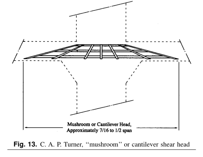
The 'cantilever' reference you refer probably is in reference to what Turner called "mushroom" cantilever shear head:

mushroom_rmzpy9.png


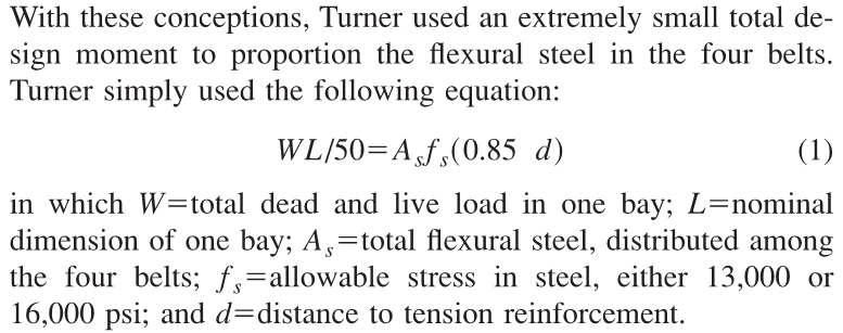
Turner's 4-way 'belt' reinforcement system was based on extremely low total design moments:

turner_zaytlh.png


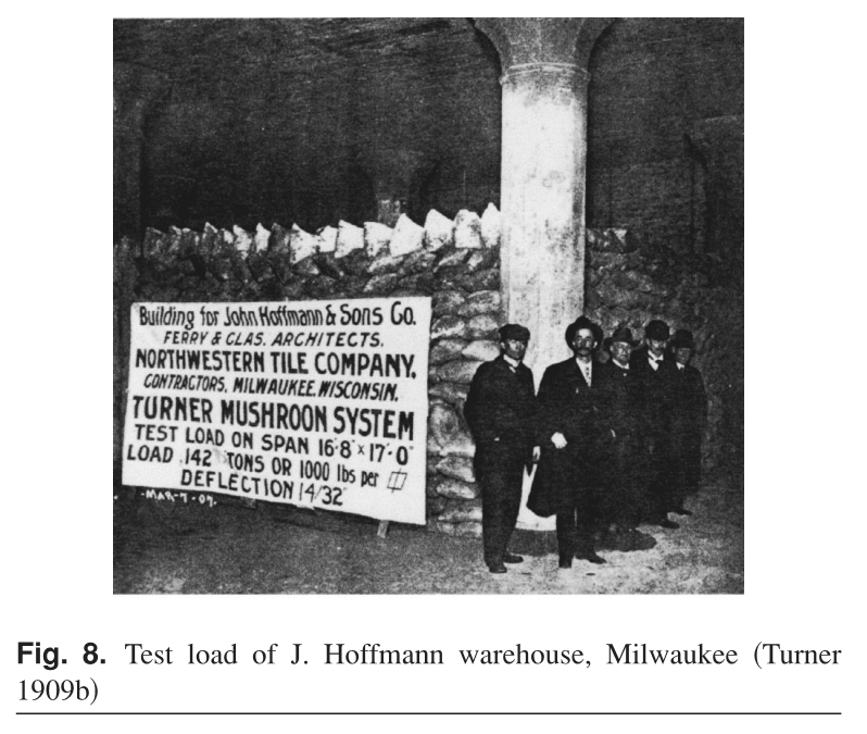
Interestingly, many of his floor systems were load tested to very significant over-loads:

turner2_creojn.png


I think it was the 1963 edition of ACI 318 code that deleted the previous requirement where you could design for 80% of the total static design moment in 2-way flat slabs.
 
Hi @hokie66 and @Ingenuity,

Thanks for your feedback. This is indeed the C.A.P. Turner mushroom system described by @Ingenuity! To answer your question, the slab thickness seems to be 12 inches, and the intended live load would be 50 PSF. The dashed lines on the plan snippet represent bottom steel and the solid lines represent top steel. The bars are detailed as "boat-shaped" whereby longitudinally they shift from top to bottom and then from bottom to top via diagonal sections (as per all reinforcing bars during that era).

From my understanding the C.A.P. system has 4 directions instead of the modern 2 directions we are used to dealing with, which is what causes the confusion. The intended opening is planned in the intersection of the bottom steel of the diagonal bands, which would normally be the intersection of the middle strip in a modern slab system and therefore usually not impose much of a problem... However, I also agree with @hokie whereby a slab does not see the direction of rebar, it only sees the rigidity defined by the column locations, and would want to span in the smallest direction (i.e. orthogonally, not diagonally). Also, in adding the opening, we are removing any load that would otherwise be there.

All that said, would you gents agree with the following: Doing a finite element analysis of the slab with the opening input, and verifying the redistribution of stresses. From there, I can verify if the existing remaining rebar is capable of resisting the moments that the program gives me, in order to see if strengthening is required?

Finally, if there is any strengthening to do, what would be the best way to do it without being too destructive (i.e. since the structure is already in great shape)?

Thanks in advance, everyone has been a great help so far.

 
Structural-eng. ... I am currently working on a project whereby we are required to evaluate and potentially reinforce an existing concrete slab due to the creation of a [b said:
future 4 feet by 4 feet future opening for electrical conduits[/b]. We are dealing with a very old building that is in good shape (built in 1930). The challenge here, is that the rebar has been placed both orthogonally and diagonally]

What is the reason for such a big opening ? I fully agree with JAYROD. In past, i experienced that MEP people , architects demanding "exaggerated" openings which are compromising the behavior and strength of the structure. I always simply rejected .

If the opening is for future electrical conduits, drilling of several small bore holes should do the work..

I will suggest you to speak with electrical people and try to see the real demand for the no. of holes rather than compromising the behavior of 90 years old structure .

 
@HTURKAK the opening is for massive electrical conduits, it is not standard wiring - hence the reason for such a large opening. There is a new set of big transformers being placed at the floor below and the conduits are associated with those. There is a bit of room for shifting the opening but not much. That is why the idea is to do an analysis and to reinforce as required. Seeing that it is placed at the intersection of the middle band bars and not column strip bars, I think it is currently located in the best position. My question is how can we reinforce such a situation.
 

My suggestion will be,

i) Shoring of the subject slab with props and lifting about equal to elastic deflection,

ii) Braking of the opening with dimensions 5'X 5',

iii) Prepare a heavy steel frame of L sections with interior dimensions 4'X 4' , and weld the cutted rebar ends to the flange of L frame ,

iv) Fill the perimeter opening with high strength repair grout,

v) Take out the props after new concrete get hardened .

I want to express that , still I suspect for the dimensions of such an opening..

Good Luck..

 
The slab thickness is 12", but don't those long dashed lines running left to right represent thicker bands on the column lines?

I don't see that something like HTURKAK's frame or the curb suggested by others, just around the opening, does much good.
 
@hokie66 the dashed lines represent bottom steel placement, no thickened areas.
Thank you all for your advice so far. I am eager to hear other ideas for reinforcement of such an opening.
If reinforcement is required based on analysis, how would we detail an upturn beam or frp strips? In other words, where would they start and end? Would we simply only extend such reinforcements from the perimeter of the opening to the column strips? Or would we have to find a way to bring them all the way to the columns and connect into the columns? See my image below for my first option. The blue lines represent either upturn beams or frp. Awaiting your feedback

Thank you all un advance, much appreciated
 
 https://files.engineering.com/getfile.aspx?folder=dbb0b4e4-9d0f-40b7-8a47-3a820ad76319&file=20201011_064814.png
Trying to think out the box, this might be completely unpractical in your specific situation, but you asked for more ideas:
Does the project really need the floor space directly adjacent to the proposed opening?

If not, you could remove whole middle area of the slab completely (the 13'-10" wide zone) and only keep the area with orthogonal bands / column strips. Then the column strips only need to carry themselves plus the loading directly above from column to column (which they are probably able to do), since there are no redirected loads from adjacent areas to take on any more. Lots of space for lots of cables and ducting [smile]

Some things to take into account if you want to take this route:
[ul]
[li]The adjacent 'panels' of the floor (other side of the columns in every direction) should be checked since they go from a continuous condition to an edge condition in the continuous slab system[/li]
[li]Does the floor has any function in the lateral stability of building and if so, what's the effect of taking a big chunk out of it?[/li]
[li]Securing the big void you just made with a parapet or something[/li]
[/ul]
 
Status
Not open for further replies.
Back
Top