Continue to Site

Eng-Tips is the largest engineering community on the Internet

Intelligent Work Forums for Engineering Professionals

  • Congratulations KootK on being selected by the Eng-Tips community for having the most helpful posts in the forums last week. Way to Go!

How would this drawing be measured?

Status
Not open for further replies.

Mitchapalooza88

Industrial
Jan 31, 2017
3
Hello all,
I have an interesting situation that I will try to simplify.

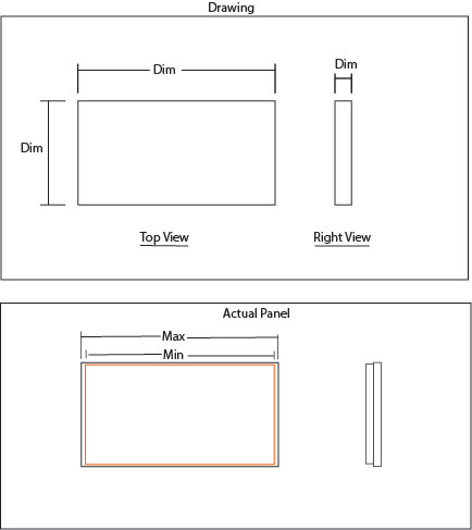
In the picture below I have a simple example of what would be a panel. There is a length, width, and thickness dimension. Each dimension has a tolerance. The top box is what our drawing looks like.

The bottom box is how the panel actually looks when it is manufactured because it is two materials bonded together with each different tolerances of their own.

The question would be, what is the proper method for measuring the width of the panel from a quality standpoint? Would the maximum tolerance be taken from the larger step and the min tolerance be taken from the smaller step in the panel?

In my opinion since it is in the top view, it would be the outermost dimensions that have to meet the tolerance. Or the profile of the panel. There are no perpendicular callout or anything saying the edges have to be 90 degrees.


If this is confusing I can try to explain more. Its a tricky thing to convey.

Panel_Example_o3ywbw.jpg
 
Replies continue below

Recommended for you

The answer depends on what you are trying to do, which is not at all clear.

What two materials?

Do they shrink differently? With temperature? With humidity?

If the panels are different actual sizes, would it be acceptable to assemble them with two edges flush, or do you expect them to be centered?

Could you bond them, then rout or mill the edges to make them match?

... etc.

A proper drawing needs to make all that, and more, clear.
Think of it this way;
Your current drawing depicts what you want.
A better drawing would depict exactly what you will NOT accept.


Mike Halloran
Pembroke Pines, FL, USA
 
If the drawing is as you've shown (or similar), then the given dims apply at all cross-sections throughout the depth, not just the silhouette. The ASME Y14.5 standard says that both the "actual local size" and the "actual mating envelope" must be within a given size tolerances (with some exceptions).

Also, you point out that there is no tolerance on the perpendicular corners. Be aware that that could be a problem. The entire part could be skewed into a parallelogram and it would still meet that print, assuming that each individual size tolerance is met.

John-Paul Belanger
Certified Sr. GD&T Professional
Geometric Learning Systems
 
As currently drawn it is ambiguous and open to the interpretation of whomever is doing that particular inspection.

If the condition of the edge is important then the drawing should be made clear and unambiguous.
 
Belanger said:
If the drawing is as you've shown (or similar), then the given dims apply at all cross-sections throughout the depth, not just the silhouette. The ASME Y14.5 standard says that both the "actual local size" and the "actual mating envelope" must be within a given size tolerances (with some exceptions).

Also, you point out that there is no tolerance on the perpendicular corners. Be aware that that could be a problem. The entire part could be skewed into a parallelogram and it would still meet that print, assuming that each individual size tolerance is met.

Yes thank you, this is exactly what I was looking for. That was my arguement is that technically the entire panel could be skewed and still meet the drawing.
 
And if you need "ammunition" to back up the idea of squareness on the corners (or lack thereof), then refer to ASME Y14.5-2009 paragraph 2.7.4, especially the first two sentences of that paragraph.

John-Paul Belanger
Certified Sr. GD&T Professional
Geometric Learning Systems
 
Status
Not open for further replies.

Part and Inventory Search

Sponsor