Continue to Site

Eng-Tips is the largest engineering community on the Internet

Intelligent Work Forums for Engineering Professionals

  • Congratulations KootK on being selected by the Eng-Tips community for having the most helpful posts in the forums last week. Way to Go!

How would you design this Glulam beam? 2

Status
Not open for further replies.

ThomasH

Structural
Feb 6, 2003
1,176
Hello

I am working with something that has me wondering how others would view this issue.
It concerns the glulam beam that you can see (simplified) in the figure bellow. It is a simply supported beam with an additional glulam "column" from 1 to 2. The blue lines are steel bars slightly prestressing the truss.
Figure_1_l86x1s.png


The load on the beam will result in tension in the steel and compression in the column. My impression from looking in different documents is that this structure is usually analyzed using beams or other line elements. But due to the circumstances I am using plate elements för the top beam. The figure is a simplification of reality but the top beam is 215 mm thick and 1.6 m high. What happens is that it buckles out of plane at location 2. And if I use non-linear analysis with initial imperfections I get a significant moment in the connection at 1. That of cource depends on the size of the imperfections.

My questioon is, how would you approach this structure? The reason I ask is because I can't see non-linear FEM-analysis as a typical design method. And I don't see how you can find this effect without it.

As always, ideas are appreciated.

Thomas
 
Replies continue below

Recommended for you

I would determine the vertical stiffness of your "column" from 1 to 2 by looking both at the elastic shortening of the glulam (though it's probably negligible) and the elastic stretch of the steel. Then convert your model to a pin, vertical spring, roller support scheme and analyze the glulam. Then follow the load through the load path and iterate as needed until everything converges nicely.

Then I'd detail bracing at 1 and 2 based on a nominal load - maybe 2% of M/d.
 
OP said:
The reason I ask is because I can't see non-linear FEM-analysis as a typical design method.

Quite right.

OP said:
And I don't see how you can find this effect without it.

In the context of a hand calc / simplified model, "finding it" really means anticipating it and making provisions to deal with it. A lot of these systems go unbraced for aesthetic reasons. If taking that approach, I'd apply 5% of the rod tension as a lateral load at [2} and ensure that can be dealt with via twist in the beam and rotational restraints at the beam ends.
 
I would not normally consider this a FEM type solution and would design it using simple statics. The steel tensioning rods are stiff enough that I wouldn't consider second order effects. Tricky part is the 'wobbly' connections to the stub column and the steel tie rod.

Rather than think climate change and the corona virus as science, think of it as the wrath of God. Feel any better?

-Dik
 
I recall a problem like this in Univ. It was a hand calc. Your steel truss elements basically help deal with deflections. Unless you have a method to measure the applied prestress in the rod, I doubt it does much more. The example I recall was a moderate span bridge. I don't see this as a second order problem either unless this is something other than typical rod material one can find easily.
 
I view this similar to Brad805. At the levels of prestress typically involved, it tends to have more in common with a truss than a prestressed element.

It may also be worth noting that OP's stability concern is part of what often leads folks to use a steel post rather than a wood one. A steel post is more readily moment connected to the beam for out of plane forces. At the least, if using a glulam post, this suggests a preferable orientation for the knife plate.
 
Is the top of this 1.6 m deep beam laterally braced?
 
You need sufficient bracing to prevent the beam rotating to get a stable system, and a moment connection at the top of the post, then the post is simply a cantilever with an axial load applied. Apply some proportion of the axial load laterally at the bottom of the post to size the restraining system.

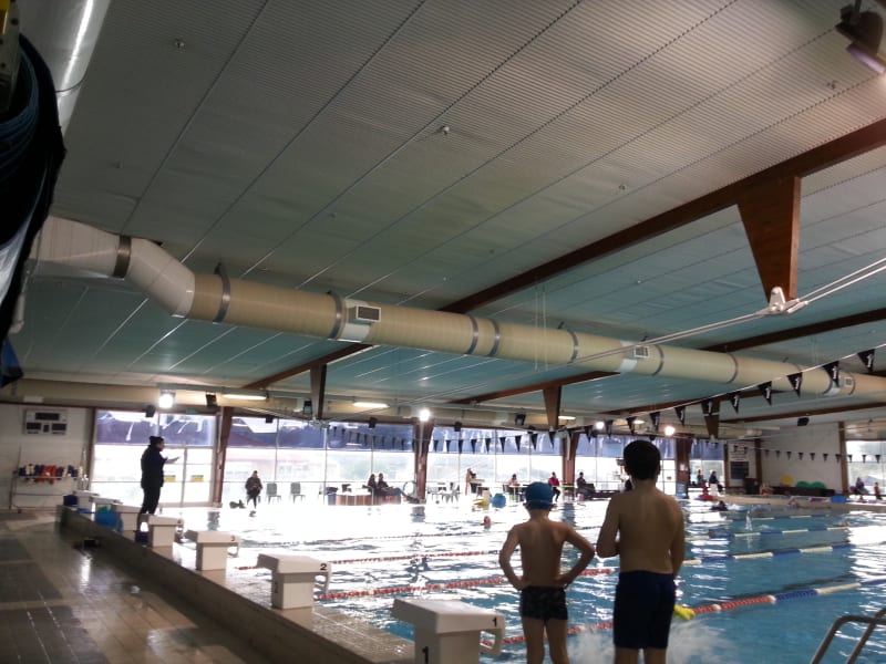
Here's an example, I believe this was retrofitted after the portals sagged too much due to the humidity and temperature in the pool. Epoxied dowels installed to the underside of the beam from memory.
20140722_160851_crwiqj.jpg
 
The beam is laterally braced at the top. The prestress is only the slightly precamber the beam and the connection at pos 1 has a moment capacity.

I won't comment a lot just yet but I very much appreciate your input.

Thomas
 
The beam is laterally braced at the top

The beam needs to be restrained against rotation along its axis, not just laterally restrained. Might just be a matter of terminology, but pointing it out just in case in the absence of any detail how you are achieving the restraint that we are actually talking about the same thing [glasses].
 
Agent, I agree with rotational restraint, therefore my question is, how was that provided in the pool example you posted? It seems rotationally quite flexible.
 
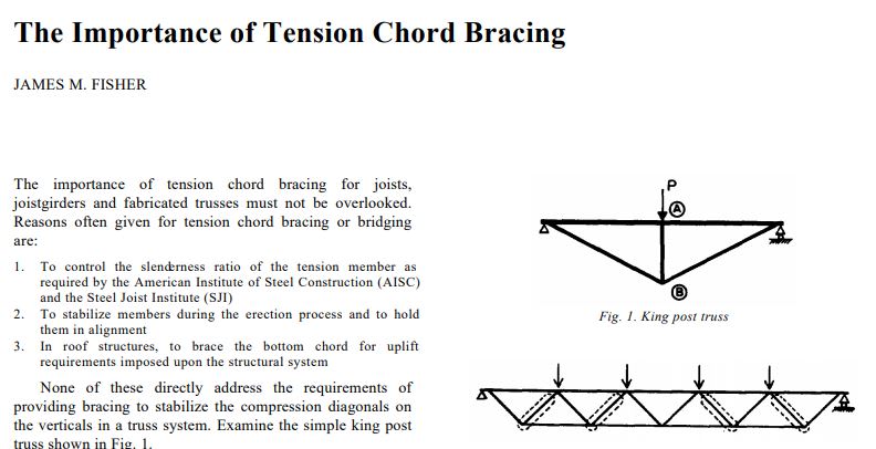
Another finer point regarding the bracing: for full span, lateral torsional buckling, the effective depth of the beam is likely to be the distance between the top of the beam and the tension rods. This may change the calculus on whether or not conventional top flange bracing is actually effective for LTB (60% depth framing tying in etc). At the least, it warrants a little extra consideration. The king post truss is actually the classic example for the need for truss bottom chord bracing as discussed here: Link

C01_dfc4an.jpg
 
Sorry, my explanation was erroneous.

The structure buckles out of plane at position 1. Position 2 is restrained out of plane. So the stability is dependant on moment capacity in pos 1.
The structure becomes very sensityve to imperfections, hence the thought about non-linear analysis.

Thomas
 
Sounds like you're in good shape then. Create that moment capacity at 1 and you've basically got phamENG's original recommendation.
 
I am still interested in thoughts regarding the stability. For example, the risk for the glulam beam to buckle out of plane due to the compression from the column.

Thomas
 
jayrod12 said:
...how was that provided in the pool example you posted? It seems rotationally quite flexible.

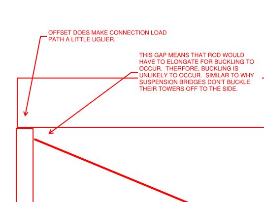
I can't resist speculating on some options because, well, it's super interesting:

1) Some serious beam torsional restraint offered by whatever's in the ceiling.

2) The raw weight of the big triangle things may well be enough to tip the stability scale in the right direction given that LTB rotation will be constrained to occur at the level of the roof deck.

3) The super clever mechanism shown below which, alas, has a tradeoff. There's no free lunch in Newtonian physics.

C01_rmccla.jpg
 
From a rotation perspective, I assume the beam is rotationally restrained at its ends, but the only continuous bracing is lateral at the top surface. Perhaps rotational restraint, such as fly braces, is possible? In such a case, though, I would be surprised to see a large moment at #1 I see now that there's lateral bracing at Location #1.

I'm not so sure you're off base by employing some FEM here to determine the moment in this connection. Your d/b ratio is 7.44. In my experience, any ratio over 6.5 is considered susceptible to LTB unless there's bridging/blocking in place to rotationally restrain the beam. Considering that the beam alone is likely susceptible to LTB, and that steel rods will only make this less torsionally stable, I'd probably be looking beyond rules of thumb to determine the moment resistance of this connection.

The beam's bottom fibers are moving laterally as the beam torsionally deflects, but the tensioned steel rods are resisting this behaviour, resulting in the moment at Location #1. If you can rotationally restrain the beam at Location #1, that would be the ticket. If not, then I'd be designing a robust moment connection there. Perhaps steel plates on both sides of the "column", running up the sides of the beam as well, with oodles of fasteners?
 
how was that provided in the pool example you posted?

Looking at the drawings I have they had 900 deep rafter with 450 deep purlins framing into the sides of the rafters from each side. So presumably they utilised these to take out any rotation (no detail provided on the end connections to these, but wedged between 2 x 450 deep purlins would go fair way towards limiting any rotation I would say even with fairly nominal connections).

Not my design so I cannot comment further on design apart from what is implied, I only did a condition survey of the entire complex many years after these fixes were in place. According to the drawings the repairs were due to some delaminations in the glulam as well as the deflection issues I noted earlier.
 
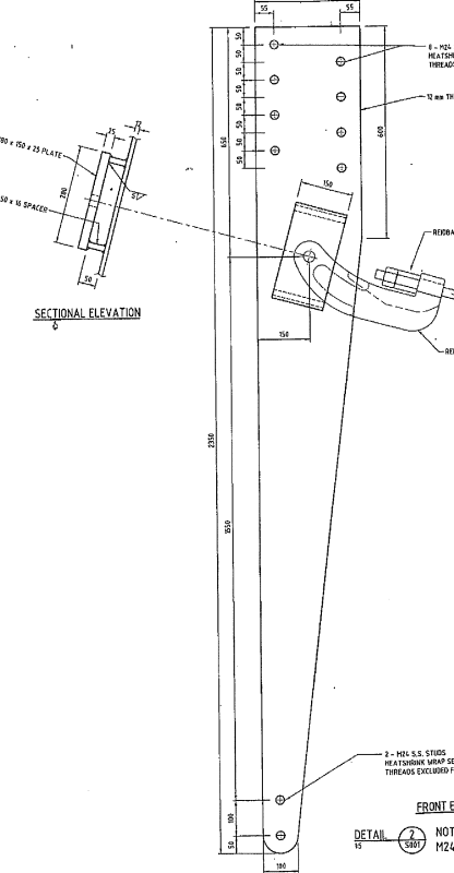
Kootk, they had these plates which took the beam axial reaction more or less back to the CL of the rafter with a smaller point load further down the column.
image_nshqzr.png
 
Sweet... thanks for sharing that Agent. Any chance you've got the detail where the rods hit the beam ends?
 
Status
Not open for further replies.

Part and Inventory Search

Sponsor